Controlling 3 way SMC solenoid valve with external power source [SOLVED]

Hello,

I am trying to prototype/setup a testing environment to manipulate some 3 way SMC solenoid valves through LabVIEW using an Arduino UNO. I am doing this to learn something more about Arduino and electronics while I wait for the wheels of bureaucracy to submit and then approve the requisition of the actual National Instruments cards we will actually need to use eventually. Yay regulations!

At the moment, I am stuck at a very rudimentary part of the process, i.e. just getting the sketch to open and close the valve.

The valve I am using is the SYJ500 model as shown in this documentation:

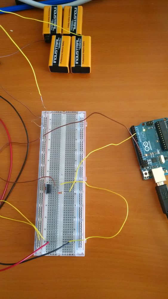
The solenoid requires fairly low wattage (<1 Watt) but fairly high voltage for Arduino projects (24 V) so I have linked 4x 9V batteries in series and tested them to see that they are succesfully outputting sufficient voltage.

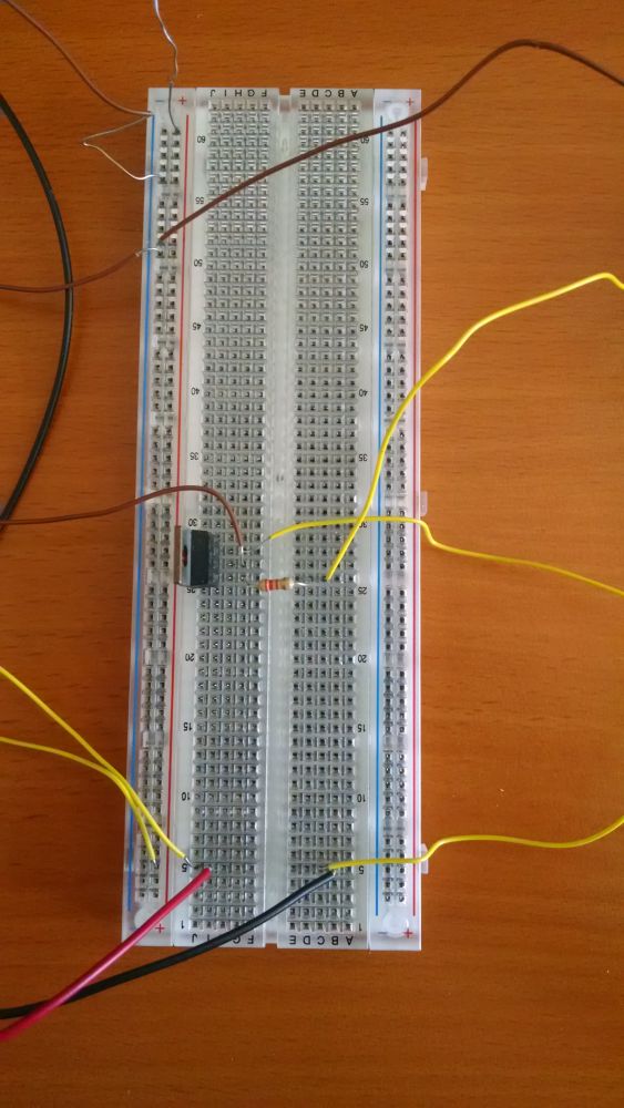
I will be able to upload a diagram/photo of the wiring setup tomorrow when I return to the lab, but hopefully the following description may clarify:

The Arduino is connected to the circuit board through output pin 4, which leads to a 3.3k resistor before going to the Darlington transistor (I believe a TIP120). The emitter is connected to the battery ground. The collector pin is connected to the positive solenoid wire, and the negative solenoid wire is connected to the positive battery terminal.

I have essentially tried to implement the wiring as in the attached motor diagram, only emitting the diode explicitly as I believe there is a one way diode in the solenoid electronics themselves.

Once I wire it, the LED on the solenoid lights up, which actually uses 75% of the power the solenoid draws, so I believe it is definitely pulling sufficient power. However, my sketch seems to not actually turn the solenoid valve. The sketch I am using is below:

int solenoidPin = 4;    //This is the output pin on the Arduino we are using

void setup() {
  // put your setup code here, to run once:
  pinMode(solenoidPin, OUTPUT);           //Sets the pin as an output
}

void loop() {
  // put your main code here, to run repeatedly:  
  digitalWrite(solenoidPin, HIGH);    //Switch Solenoid ON
  delay(1000);                      //Wait 1 Second
  digitalWrite(solenoidPin, LOW);     //Switch Solenoid OFF
  delay(1000);                      //Wait 1 Second
}

It just now occurs to me that it may simply be the case that I need to connect the Arduino ground to the circuit ground, but I will put up this post anyway as I cannot test at the moment and in case there may be some other issue that I am overlooking. If I happen to test it and this resolves the issue before I get any responses, I will try to close the topic.

Any and all help/advice is appreciate, I have a little experience with circuits but definitely am an Arduino beginner. Thanks!

motor_diagram.png

Connect the grounds.

And I guess you meant the opposite to this:-

The collector pin is connected to the positive solenoid wire, and the negative solenoid wire is connected to the positive battery terminal.

Edit: 4 x 9V batteries in series is 36V. If I were you, I'd use 3 batteries, 27V.

Hi,
Have you connected gnd of the supply to gnd of the arduino.
Do you have a DMM to see if pin 4 is going HIGH and the collector LOW?
What is the voltage across the solenoid when it is supposed to be ON and OFF.

Tom.... :slight_smile:
PS. Can you post a picture of your project please?

Hey guys, thanks for the quick responses!

I've managed to take a couple pictures of the setup. The brown wires should all be connected to ground, and the yellow wires should be carrying positive current.

Also, a correction: the transistor is not a TIP 120, it is a Fairchild MJE3055T TO220. (https://www.fairchildsemi.com/datasheets/MJ/MJE3055T.pdf)

@TomGeorge: The voltage across the solenoid when it is on is ~34 V. My issue is that I cannot get it to turn off via the Arduino : )

And, indeed, the collector is LOW when pin 4 is HIGH (4.9 V) - however, I am not sure why or how to resolve this. Is it possible the resistor (3.3k) is too strong?

Thanks!

Hi,

Place the EMITTER of the 2N3055 to gnd, the BASE to the arduino via the resistor.
The COLLECTOR of the 2N3055 to one side of the solenoid, the other side of the solenoid to battery.

If BROWN is GND then you have COLLECTOR to GND.

The 2N3055 looking from the front is BASE,COLLECTOR,EMITTER...Note the Heatsink Tab is also COLLECTOR.


You also need a diode such as 1N4004 connected across the solenoid terminals, CATHODE of the diode to the SUPPLY side of the solenoid, the ANODE connected to the terminal of the solenoid that connects to the COLLECTOR.
To protect the rest of the circuitry from Back EMF of the solenoid, when switching off.

I will be surprised if it will work consistently due to the low gain of the 2N3055, but try it.

Tom.... :slight_smile:

dzaks:
The Arduino is connected to the circuit board through output pin 4, which leads to a 3.3k resistor before going to the Darlington transistor (I believe a TIP120). The emitter is connected to the battery ground. The collector pin is connected to the positive solenoid wire, and the negative solenoid wire is connected to the positive battery terminal.

sorry, but this is wrong.

battery positive to the positive of the solenoid. not the negative.
solenoid ground to the collector of the TIP120
emitter of the TIP120 to ground. as you have it.

Great, thanks for the help!

It looks like the script is working; I am seeing a voltage jump across the solenoid. However, it seems like it is simply switching a 1.5 V difference - the DMM across the solenoid shows a jump from ~ 33 V to ~ 34.5 V.

I am not sure if I am missing something fundamental - am I using an inappropriate transistor, or something else?

Thanks,
Daniel

P.s. regarding the flyback diode, I decided to omit this as the circuit diagram for the solenoid valve in question shows that it has a built in diode as shown. Also, when I attached a 1N4001 as suggested, it very quickly began to overheat.

Hi,

P.s. regarding the flyback diode, I decided to omit this as the circuit diagram for the solenoid valve in question shows that it has a built in diode as shown. Also, when I attached a 1N4001 as suggested, it very quickly began to overheat.

Hmm. okay, just make sure that the positive marked terminal of the solenoid goes to battery positive and the negative terminal of the solenoid goes to the transistor COLLECTOR.
Did you recheck and change your wiring to the 2N3055?

Can you do a test for me.
With the arduno output OFF or LOW, measure the following voltages.

  • Measure from GND to arduino output.
  • Measure from GND to transistor BASE.
  • Measure from GND to transistor EMITTER.
  • Measure from GND to transistor COLLECTOR
  • Measure from GND to Solenoid Neg terminal.
  • Measure from GND to Solenoid Pos terminal.

Then with the arduino output ON or HIGH, measure the voltages again.

Thanks, it sounds a lot, but we need to see how your circuit is performing.

Tom..... :slight_smile:
Can you post another picture of your project now thank-you?

I did rewire the circuit as suggested; I actually had it that way originally, but then I thought I got the COLLECTOR and EMITTER pins switched in my head.

No problem on the readouts.

With the Arduino OFF/LOW:

  1. GND to arduino output (pin 4) : 223.6 mV
  2. GND to transistor BASE: 222.6 mV
  3. GND to transistor EMITTER: 1.1 mV (~0 V)
  4. GND to transistor COLLECTOR: 0.761 V
  5. GND to solenoid Neg Terminal: 0.761 V
  6. GND to solenoid Pos Terminal: ~ 34.2 V

With the Arduino ON/HIGH:

  1. GND to arduino output (pin 4) : 4.89 V
  2. GND to transistor BASE: 0.6 V
  3. GND to transistor EMITTER: 1.3 mV (~0 V)
  4. GND to transistor COLLECTOR: 0.75 V
  5. GND to solenoid Neg Terminal: 0.75 V
  6. GND to solenoid Pos Terminal: ~ 33.7 V

Which are kind of weird results...I can't quite make sense of them. The current into the resistor from the arduino is reading about 2 mA, and the current through the negative terminal of the solenoid is reading about 20 mA, if that helps.

Could it be a burnt/damaged transistor? Or simply an inappropriate transistor?

With the Arduino OFF/LOW:

  1. GND to arduino output (pin 4) : 223.6 mV
  2. GND to transistor BASE: 222.6 mV
  3. GND to transistor EMITTER: 1.1 mV (~0 V)
  4. GND to transistor COLLECTOR: 0.761 V
  5. GND to solenoid Neg Terminal: 0.761 V
  6. GND to solenoid Pos Terminal: ~ 34.2 V

This indicates that the transistor might be short-circuit, or something's wrong with your wiring. With 222mV at the transistor base, the collector should read a high value roughly equal to the supply voltage.
The transistor measurements, #3, indicate that the transistor is not switching off.

A new picture of your circuit is in order, to double-check connections.

Sure, no problem. I've tried to move the wires to make the connections as clear as possible. Please let me know if the link does not work.

Thanks!

dzaks:
Sure, no problem. I've tried to move the wires to make the connections as clear as possible. Please let me know if the link does not work.

https://drive.google.com/open?id=0BzS7sv5bS7GlTE1vU1dWYzFKb1k

Thanks!

I get 'Access Denied' for your image. It's actually better to post your image here on the forums anyway, instead of on another site.

If you edit your post using >"More" >"Modify", below the text box is an option to add attachments.

Yeah, I was concerned about that. I will just attach it, hopefully this works now.

Yep, that worked:-
(Right-click and "View Image" or similar for full size.)

Everything looks OK to me.

I assume that the wires going off to the right are to the Arduino, with brown to Arduino ground, and the ones at the top left come from the batteries, with the red and black to the solenoid.

It's looking more and more like a dead transistor, shorted between collector and emitter such that it can't turn off. If you remove the resistor, does the solenoid switch off? (Leave the other wires exactly where thay are.)

Edit: I just noticed that the bare ends of the wires going into the breadboard for the transistor's collector and emitter look like they could be touching. Are they?
(I usually only bare just enough wire to go into the breadboard holes, so no bare wire is exposed outside the breadboard.)

Removing the resistor does not switch off the solenoid, so it seems like you may be correct. I will try replacing the transistor tomorrow when the inventory is unlocked, and see if that improves the outcomes.

dzaks:
Removing the resistor does not switch off the solenoid, so it seems like you may be correct. I will try replacing the transistor tomorrow when the inventory is unlocked, and see if that improves the outcomes.

So I assume those wires weren't touching.

If you feel like it, you could do a final test to confirm the diagnosis - remove the transistor and measure the resistance between collector and emitter. If you test on a medium range, say 20K, the transistor should read infinite resistance.

Incidentally, that transistor is massive overkill for a ~20mA load. Even a simple BC547 small signal transistor would do the job easily. Note that the pinout is different though. From left, looking at the flat side with leads downwards, a BC547 is C-B-E.

So I'm no longer certain it's the transistor; the resistance does read near infinite at most ranges (it was reading at around 2 M-Ohm the first time, now it is showing infinite across all levels. However, I also found that I did have an unused BC547 lying around outside the supply room, and rewired for that, with the same results.

I will give another crack at it tomorrow morning, but this is getting a bit mysterious. I may be fundamentally misunderstanding the power requirements of the solenoid valve.

Hi,
Another picture of your connections to the transistor BC547 would be great also.

Thanks.. Tom. :slight_smile:

A true mystery. The other thing that was in my mind, unlikely as it is, was a short in the breadboard.

Regarding power requirements, the datasheet claims 0.4W with light. At 24V, that's only 17mA. An LED on it's own usually draws 10mA to 20mA. If the LED draws 10mA, that only leaves 7mA for the actual solenoid coil. And solenoids usually use considerably more than that.

Still, quite puzzling. I wonder if it is a problem with the breadboard?