I got my hands on this old camera in a housing with two motors. It lets the camera have a dome-like view, spinning 360 at the base, and a little more than 90 up and down.
Here he is stripped down. The two motors each seem to have built in shields. Each shield has 4 black wires that come down and combine into an 8-wire port.
Would it be possible to control these motors from an arduino? I understand how to run a motor with a shield and an arduino when theyre all stock parts, but Ive never hacked a decice before.
Thanks for your time, sorry if this is a basic question, I tried to do my googling first.
The clearest identifying mark I could find on the controller says
" RU E F 2 94V-0
E345288
13/37"
I tried googling that but other than "94v-0" being a flammability rating, I couldnt parse any of it.
There is also a barcode hidden underneath where I cant photograph that is "14292004" which also didnt bring anything up.
I assumed the top and bottom motors/controllers where the same, since they look nearly identical, but the barcode on the top one is "14290372", otherwise the markings and placements of components seems the same. These barcodes might be individual instead of item numbers.
Ah, well thank you so much for helping. I tried searching, but all I found was the user guide which unfortunately gives a bunch of specs for the camera itself, but nothing about the motors.
I tried to completely unscrew the motor from the base so i could get a clear shot of both sides, but one of the screws is entirely stripped.
Ah well. Maybe Ill re-assemble it all and put it in the ewaste bin. I really thought I could make something of a homemade Jibo out of this.
I found the motors described in a specs list as "silent brushless DC direct drive motors". However, Im still at a loss about the controllers. Without information on the boards the motors are connected to, is there much I can do? I dont believe the boards and the motors can be separated.
No. You have to reverse engineer the signals to and from the motor controllers. Unless there are meaningful markings that allow excellent guesses for the various connections between the boards, in general, an oscilloscope and a working camera system is needed for the analysis.
From the looks of the boards, I suspected that those would be brushless motors.
It might be possible to just use the mechanical bits, and replace the motors with steppers, which are easy to drive.
Thanks for looking for me, bur thats not it. I actually found it! Theyre here
and I even found their pin layout in a manual.
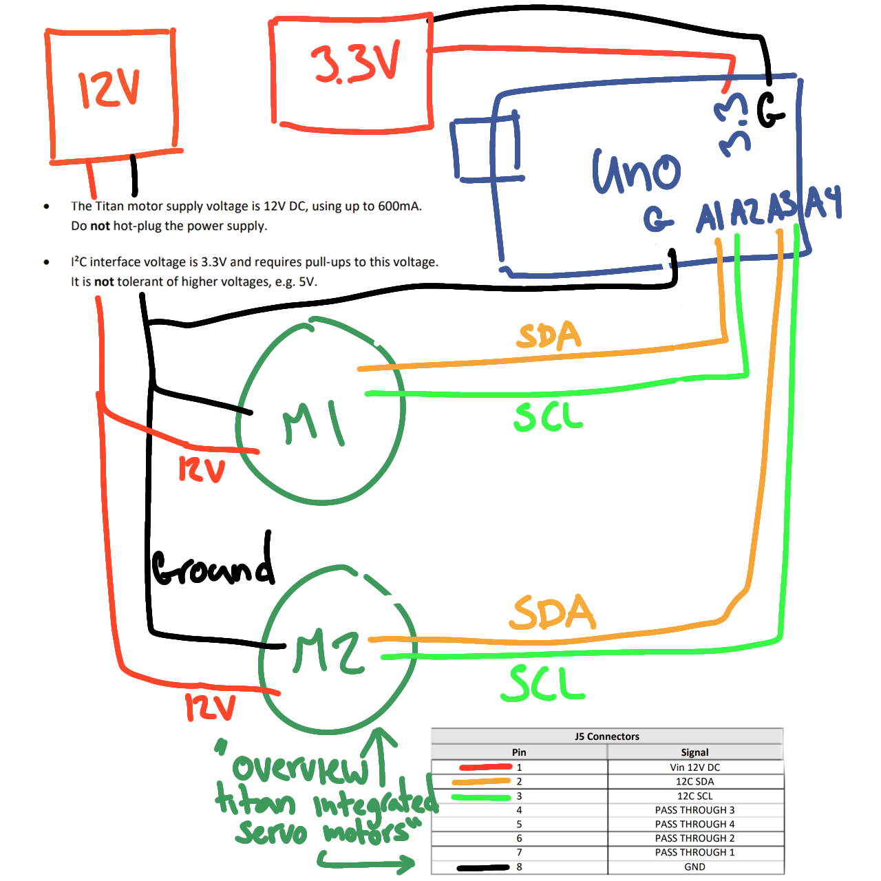
1- Vin 12V DC
2- I2C SDA
3- I2C SCL
4- Pass through 3
5- Pass through 4
6- Pass through 2
7- Pass through 1
8- Ground
Ive tried to draw up a wiring diagram for them. Granted, I fully expect it to be wrong. But the manual says the I2C wires need 3.3V and the motors themselves need 12V, so this is what I came up with.
No? I was just refrencing the nice range of motion this setup already has, if I can control the motors. Would make for a fun wiggly bot. I wasnt trying for much more.
I dont mean to be ignorant, but you can tell Im new to this. I dont understand what you mean by quoting that. The motors use a special protocol. Ive seen others using I2C to link arduinos or sensors together. What is different with a motor?
The motor isn't driven via I2C directly. The I2C signal goes to a driver chip (I'd guess one of the ICs shown on the board in post #3) which decodes the commands and converts that to the actual motor signals/voltages.
A check on the part numbers of those ICs may reveal something useful.