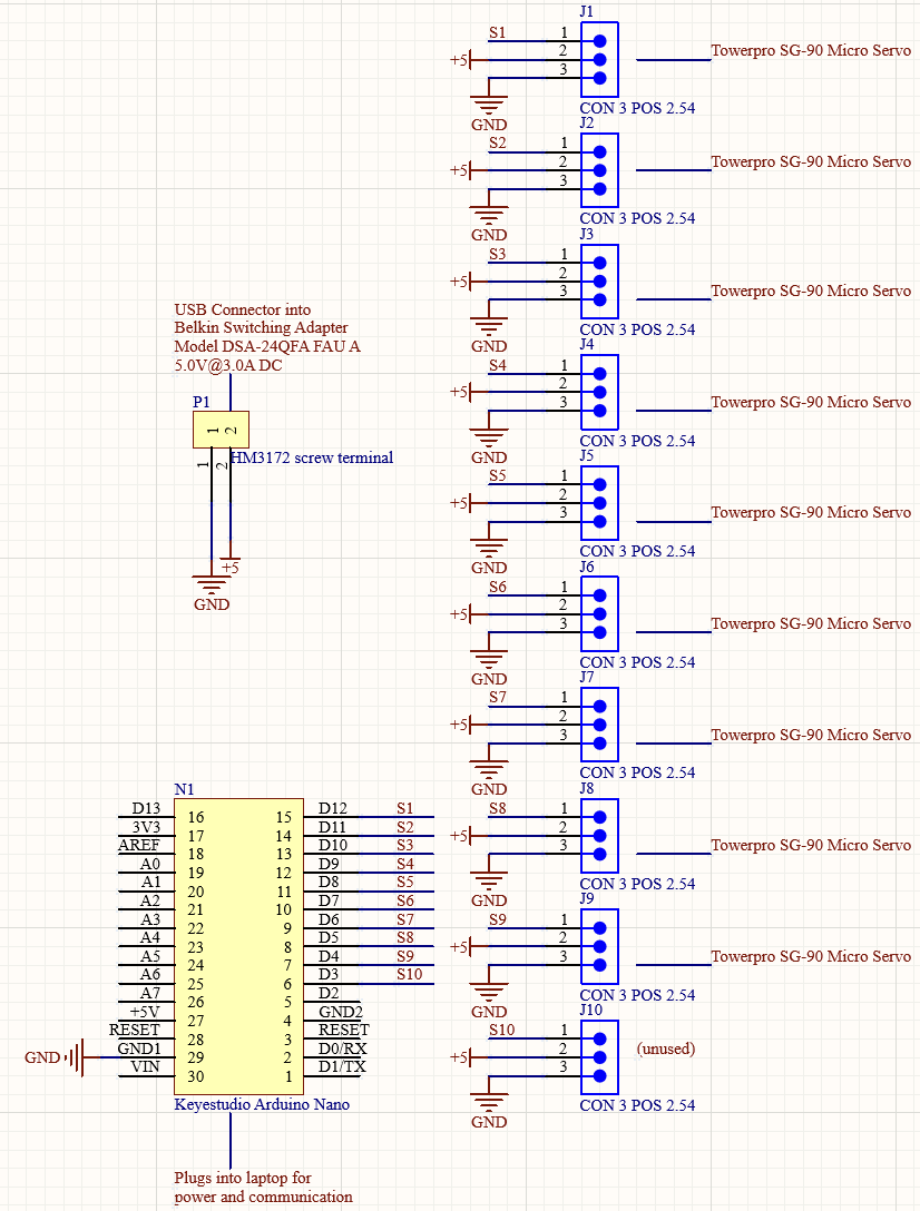
I'm building a project that features 9 servos, with a maximum practical current of roughly 3.5A, running via an Arduino nano. I've got the servos powered off their own power supply, but whenever the Arduino turns off while the servos have power, they tend to jump (I assume the board outputs some noise on the digital pins whenever it loses power).
My solution to this was going to be to use a transistor (I was thinking of a TIP122) to control current flow to the servos, so that I can essentially have a 'halt' pin on my board.
The problem is, I've sent myself down several rabbit holes trying to figure out the right transistor to use, what resistor to put on the base, etc. etc. Before I lose any more of my mind, I want to know: is it even worth trying to use a transistor? Should I use a relay instead? Is there another type of transistor I should use? Is there a whole different solution to the problem with the servos jumping?
Thanks, and let me know if you need any more information.
Assuming you have a good reason to not just power off the servo's first and then the Nano?
You could employ a routine before switching off where you do:
myservoxyz.detach() for every servo you have connected (replace myservoxyz with how you named them) .
That should stop the output an set the output pin to input again.
Can you please post a copy of your circuit, a picture of a hand drawn circuit in jpg, png?
Hand drawn and photographed is perfectly acceptable.
Please include ALL hardware, power supplies, component names and pin labels.
Can you please post some pictures of your project?
So we can see your component layout?
I see several possibilities, follow TomGeorge's request and post an annotated schematic. I and many others do not do well with frizzies. When posting the schematic note any wires over 10" / 25 cm in length.
I could power off the servos before the nano, but it gets annoying, as my power supply has a capacitor in it, so it takes a few seconds to discharge. I also just want to make it easier to temporarily disable the servos.
Also, I should've mentioned: I'm communicating with the arduino via my laptop and standard firmata.
I see a collector of a NPN tied to GND. That's confusing to see.
If you drive the base low, you drive it low compared to what? Compared to the emitter is what I know, but do you have a defined voltage level at the emitter side?
Sorry, the way I've set the schematic out is very confusing. I really should clean it up.
In this case the GND symbol really just connects to the servo grounds. I wasn't really sure how to represent a screw terminal supplying power in circuitmaker, and the transistor was added hastily for this post, so it doesn't really fit terribly well. In reality, the emitter of the TIP122 is going to the scree terminal, which represents actual ground.
If all you want to do is "stop them holding position and resist my push", which is how I would define "disable", then the .detach() function is what you need.
Your 'jump' is likely the PWM pulse from the Arduino being cut off, resulting in a pulse that is shorter than the setting for that servo. If you have control over the power to the servos in your software, that implies that you also can simply stop sending the PWM signal by detaching each servo. There should then be no jump at power down.
YMMV
That's pretty much what I need, but I'm controlling the arduino via processing running on my laptop. ATM I'm just setting the servo pins to input to halt them, but I thought it would be nice to have a single pin I can change to disable all of them.