Hi,
I have a hardware engineer and I have limited knowledge of Arduino coding. I need to sense current and voltage on my hardware with ACS712 sensor. I can measure the current correctly, but when I write voltage values on serial monitor, voltage change from 2.48 to 2.55 V. My circuit gives voltage from 0 to 5 V. I need to screen voltage as 0 to 5 volts. How could I do this? My code is here:
double Vout = 0;
double Current = 0;
void setup() {
Serial.begin(9600);
}
void loop() {
for(int i=0; i<10000; i++){
Vout = (Vout + (5/1023.0*analogRead(A0))); //for calculating the average of read values for
} //making measurement more stable.
Vout = Vout/10000; //dividing average for getting averaged voltage value
6:19:54.188 -> Voltage = 0.00 V	 Current = -13405.41 mA
16:19:55.380 -> Voltage = 0.00 V	 Current = -13405.41 mA
16:19:56.608 -> Voltage = 0.00 V	 Current = -13405.41 mA
16:19:57.834 -> Voltage = 0.88 V	 Current = -8659.27 mA
16:19:59.128 -> Voltage = 2.21 V	 Current = -1435.18 mA
16:20:00.429 -> Voltage = 5.00 V	 Current = 13622.44 mA
16:20:01.757 -> Voltage = 5.00 V	 Current = 13623.98 mA
16:20:03.053 -> Voltage = 5.00 V	 Current = 13623.97 mA
initially A0 is to GND then changed to 5V
I don't have a ACS712 connected
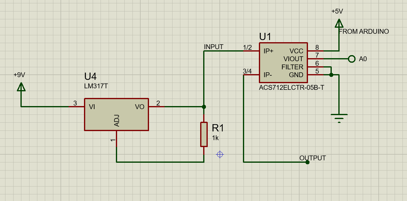
can you upload a schematic of the circuit?
if I connect a ACS712 so
ACS712 GND to UNO GND
ACS712 VCC to UNO 5V
ACS712 OUTto UNO A0
i get
16:27:51.390 -> Voltage = 2.48 V	 Current = 15.08 mA
16:27:52.718 -> Voltage = 2.48 V	 Current = 14.72 mA
16:27:54.014 -> Voltage = 2.48 V	 Current = 14.33 mA
As @Idahowalker has said we need a chematic - even if its something as simple as a pencil sketch.
we also need to know EXACTLY what hardware you are using - with a link to a data sheet or suppliers documentation.
Including - particularly - the "arduino"
In your code you are averaging 10,000 values; really its better to use a power of 2 for your "Count" - and 64 is plenty
double Vout = 0;
double Current = 0;
int Count = 64;
long Vsum; //aggregated values read from adc

and
void loop() {
Vsum=0;
for(int i=0; i<Count; i++){
Vsum += analogRead(A0); // add em up as integers
delay(27); //chosen to avoid mains frequency readings; or eg 7 or 13
}
Vsum = Vsum / Count;  //dividing average for getting averaged voltage reading value
Vout = Vsum *5.0 /1024;

//print the reading.
double Vout = 0;
double Current = 0;

void setup() {
Serial.begin(9600);
}

void loop() {

for(int i=0; i<10000; i++){
Vout = (Vout + (5/1023.0*analogRead(A0))); //for calculating the average of read values for
} //making measurement more stable.
Vout = Vout/10000; //dividing average for getting averaged voltage value

Current = (Vout - 2.48) / 0.185 *1000;

Serial.print("Voltage = ");
Serial.print(Vout,2);
Serial.print(" V");
Serial.print("\t Current = ");
Serial.print(Current,2);
Serial.println(" mA");
}
"Grounded A0" means the input of the current sensor not connected. "The 2.48 V" comes from ACS712 properties. When there is no connection, ACS712 output gives 2.5, but for mine, it gives 2.48.
yes, but my sensor idles at 2.48.
The MAIN PROBLEM THAT I AM ASKING is voltage read calculation.
I have searched and tried a lot of things but I could not measure voltage. I measure only btw. 2.48 and 2.55.
I am measuring current right, but I cannot measure voltage. The main problem is this.
The current sensor does not give you a voltage reading of the supply. The current sensor gives a voltage proportional to the current passing through the module. A formula is done to get the I.
You can measure V by putting the Vin ( on a Uno <5V) onto A1 and measuring it there.
V and I readings are done separetly with different components and different functions.
void fReadCurrent( void * parameter )
{
  const TickType_t xFrequency = 1000; //delay for mS
  const float mVperAmp        = 185.0f;
  float    ADbits             = 4096.0f;
  float    ref_voltage        = 3.3f;
  float    mA                 = 0.0f;
  float    adcValue           = 0.0f;
  float    Voltage            = 0.0f;
  float    Power              = 0.0f;
  float    offSET             = 0.0f;
  int      printCount         = 0;
  uint64_t TimePastKalman     = esp_timer_get_time(); // used by the Kalman filter UpdateProcessNoise, time since last kalman calculation
  SimpleKalmanFilter KF_I( 1.0f, 1.0f, .01f );
  /*
     185mv/A = 5 AMP MODULE
     100mv/A = 20 amp module
     66mv/A = 30 amp module
  */
  String powerInfo = "";
  powerInfo.reserve( 150 );
  while ( !MQTTclient.connected() )
  {
    vTaskDelay( 250 );
  }
  TickType_t xLastWakeTime = xTaskGetTickCount();
  for (;;)
  {
    adc1_get_raw(ADC1_CHANNEL_3); // read once discard reading
    adcValue = ( (float)adc1_get_raw(ADC1_CHANNEL_3) );
    //log_i( "adcValue I = %f", adcValue );
    Voltage = ( (adcValue * ref_voltage) / ADbits ) + offSET; // Gets you mV
    mA = Voltage / mVperAmp; // get amps
    KF_I.setProcessNoise( (esp_timer_get_time() - TimePastKalman) / 1000000.0f ); //get time, in microsecods, since last readings
    mA = KF_I.updateEstimate( mA ); // apply simple Kalman filter
    TimePastKalman = esp_timer_get_time(); // time of update complete
    printCount++;
    if ( printCount == 60 )
    {
      xSemaphoreTake( sema_CalculatedVoltage, portMAX_DELAY);
      Power = CalculatedVoltage * mA;
      //log_i( "Voltage=%f mA=%f Power=%f", CalculatedVoltage, mA, Power );
      printCount = 0;
      powerInfo.concat( String(CalculatedVoltage, 2) );
      xSemaphoreGive( sema_CalculatedVoltage );
      powerInfo.concat( ",");
      powerInfo.concat( String(mA, 4) );
      powerInfo.concat( ",");
      powerInfo.concat( String(Power, 4) );
      xSemaphoreTake( sema_MQTT_KeepAlive, portMAX_DELAY );
      MQTTclient.publish( topicPower, powerInfo.c_str() );
      xSemaphoreGive( sema_MQTT_KeepAlive );
      powerInfo = "";
    }
    xLastWakeTime = xTaskGetTickCount();
    vTaskDelayUntil( &xLastWakeTime, xFrequency );
  }
  vTaskDelete( NULL );
} //void fReadCurrent( void * parameter )
////
void fReadBattery( void * parameter )
{
  const float r1 = 50500.0f; // R1 in ohm, 50K
  const float r2 = 10000.0f; // R2 in ohm, 10k potentiometer
  const TickType_t xFrequency = 1000; //delay for mS
  float    adcValue = 0.0f;
  float    Vbatt = 0.0f;
  int      printCount = 0;
  float    vRefScale = (3.3f / 4096.0f) * ((r1 + r2) / r2);
  uint64_t TimePastKalman  = esp_timer_get_time(); // used by the Kalman filter UpdateProcessNoise, time since last kalman calculation
  SimpleKalmanFilter KF_ADC_b( 1.0f, 1.0f, .01f );
  TickType_t xLastWakeTime = xTaskGetTickCount();
  for (;;)
  {
    adc1_get_raw(ADC1_CHANNEL_0); //read and discard
    adcValue = float( adc1_get_raw(ADC1_CHANNEL_0) ); //take a raw ADC reading
    KF_ADC_b.setProcessNoise( (esp_timer_get_time() - TimePastKalman) / 1000000.0f ); //get time, in microsecods, since last readings
    adcValue = KF_ADC_b.updateEstimate( adcValue ); // apply simple Kalman filter
    Vbatt = adcValue * vRefScale;
    xSemaphoreTake( sema_CalculatedVoltage, portMAX_DELAY );
    CalculatedVoltage = Vbatt;
    xSemaphoreGive( sema_CalculatedVoltage );

      printCount++;
      if ( printCount == 3 )
      {
      //log_i( "Vbatt %f", Vbatt );
      printCount = 0;
      }

    TimePastKalman = esp_timer_get_time(); // time of update complete
    xLastWakeTime = xTaskGetTickCount();
    vTaskDelayUntil( &xLastWakeTime, xFrequency );
    //log_i( "fReadBattery %d",  uxTaskGetStackHighWaterMark( NULL ) );
  }
  vTaskDelete( NULL );
}
////
The output of an ACS712 outputs half of it's supply voltage when idle.
That is not necessarilly 2.5volt.
In your case it could be 2.48 * 2 = 4.96volt.
When you connect it to a ratiometric A/D of an Arduino (assuming UNO),
then half of Arduino's supply voltage outputs an A/D value of 512.
When you process the output of an ACS, you should not even think about voltage.
Just subtract 512 from the returned A/D value to get your positive/negative current values.
Then simply multiply that with a pre-calculated number to get current.
The ACS output range is 10% to 90% of it's supply (80% range).
That's about 1024 * 0.8 = 820 A/D values, or 410 values positive and 410 values negative.
410 values spread across the 5 Amp sensor rating (if a 5Amp sensor is used).
So 0 to 410 = 0 to 5Amp > 5 / 410 = 0.012195.
float current = (analogRead(sensorPin) - 512) * 0.012195;
410 values spread across 5000mA is about 12mA per A/D step.
Milliamp resolution with two decimal places is wishful thinking.
I would be very happy with an ACS712 reading in Amps with two decimal places.
The Arduino, with it's potentially instable reference voltage, is not very good at measuring voltage.
What are you measuring.
Wouldn't it be better to switch to an INA226 breakout board.
Leo..
@Wawa identified a number of problems using a ACS712 with the unstable reference voltage of the UNO etc
ran a test using your code of post #1 with a couple of lines added to print the power supply voltage
Serial.print(" Supply Voltage = ");
Serial.println(5/1023.0*analogRead(A1),2);
a run for a few seconds (power supply voltage 2.23 current 68mA)
11:56:41.074 -> Voltage = 2.49 V	 Current = 77.07 mA Supply Voltage = 2.24
11:56:42.409 -> Voltage = 2.49 V	 Current = 76.88 mA Supply Voltage = 2.24
11:56:43.775 -> Voltage = 2.49 V	 Current = 79.35 mA Supply Voltage = 2.23
11:56:45.141 -> Voltage = 2.49 V	 Current = 78.90 mA Supply Voltage = 2.23
11:56:46.469 -> Voltage = 2.49 V	 Current = 79.40 mA Supply Voltage = 2.23
11:56:47.828 -> Voltage = 2.49 V	 Current = 78.25 mA Supply Voltage = 2.23
11:56:49.193 -> Voltage = 2.49 V	 Current = 76.98 mA Supply Voltage = 2.23
11:56:50.525 -> Voltage = 2.49 V	 Current = 76.67 mA Supply Voltage = 2.23
11:56:51.886 -> Voltage = 2.49 V	 Current = 78.08 mA Supply Voltage = 2.23
11:56:53.239 -> Voltage = 2.49 V	 Current = 79.79 mA Supply Voltage = 2.22
11:56:54.605 -> Voltage = 2.49 V	 Current = 78.35 mA Supply Voltage = 2.22
11:56:55.960 -> Voltage = 2.49 V	 Current = 76.91 mA Supply Voltage = 2.23
some sample results taken over a range of voltages
meter       UNO
V    mA    mA     V
0     0     7     0
.59   12    18    0.57
1.55  40    48    1.51
2.56  64    74    2.52
3.57  92    103   3.51
4.76  120   129   4.38
6.98  184   197
10.2  275   290
15.9  417   430
you could do a calibration run to read the UNO measured current with 0 current flowing (7 in the above result) and subtract it future readings
however, if you require milliamp measurement with two or three places of decimals a better measurement device is required
I did use a ACS712 some years ago to measure the current taken by an extruder ram - when the current reached a set level (indicating ram was reaching the end of the extruder) the ram would be stopped and withdrawn - however, the current measured was several amps and great accuracy was not required