Custom 7 segment display power issue

I'm in the process of building a custom 8" 2 digit 7 segment display.
I have the code on a ESP32 and it is running correctly till I added the LED's
Without the LED's it ran with no issues.

Each segment has 12 LED's in series with 270Ohm resister.(14 Segments 168 total LED's)
I am powering it with 30 v benchtop power supply (Wanptek DPS305U)

After connecting the LED's now the L7805CV overheats.

The L7805CV is only powering the ESP32, shift registers, and a 5 volt 4040 fan. The LED's are all off the 30v input power.

Ignore the connection to the ESP32 in the schematic as that was the only model in EasyEDA pro had to add to the schematic. I do have the shift registers connected to the ESP32

Not sure where to go next, could someone point me in the right direction or point me as to what I did wrong.

I don't see any caps on the input and output of the 7805. Without those, it could become unstable and oscillations can occur which might make it overheat.

But why having the LEDs connected or disconnected would have any influence on that, I don't know, I don't think it should.

I also don't see any bypass caps on the shift registers. But that could cause the shift registers to act strangely, not cause the regulator to overheat.

Why is this not shown in your schematic? Is there a flyback diode connected to it to protect the rest of the circuit?

Only you know how much they sum up. If I estimate that they draw 400mA, your voltage regulator has to dissipate 10W. For sure it heats up noticeably. Heat sink is must.
Buck converter could be better option.

1 Like

How do you know it was running correctly?

It will get hot, so what do you mean by overheats

Is this a custom PCB you made?

Basically, you have this, right?

Also, you have a 30V power supply and a L7805CV-DG voltage regulator as shown below.

You mentioned that L7805CV-DG is powering:
• ESP32 (assuming 70mA, I assumed this current consumption according to this link, if everyone knows the current consumption please tell us)
• Shift registers (16 mA, see below to know how I asumme this value that include both registers)
• 5V 40 x 40 mm Fan (asumming 0.15A, can you tell us the current?)

According to the datasheet, the ULN2803 has this inside, i.e., a Darlington transistor, these transistors need a base current to be activated:

The necessary input current Ii to activate the transistor is

Let’s average this current so that Ii = 1.14 mA per channel. At the instant all 7 segments are ON, the total current will be:

imagen

The maximum current of both shift registers will be 7.98 mA * 2 = 15.96 mA or 16 mA to round up.

So, the L7805CV will supply a current equal to:
imagen

Now, let’s see the thermal considerations for linear regulators:

The difference between the input voltage and output voltage with fixed load current is energy that is dissipated by the linear regulator. Nearly all of this energy is converted to heat.

Since our system must observe physics and the conservation of energy, we can use our knowledge of VI , VO, and current to identify how power is distributed in our LDO.

The input power in our LDO is:

imagen

The power delivered to the load is:
imagen

The difference between Pi and Po is the power that is burned or dissipated by the regulator. This dissipated Power (P_D) is:
imagen

However, remember that Ii roughly equals to Io, so
imagen

PD is almost entirely heat dissipated by the linear regulator.

Now if we have Vi = 30V, Vo = 5V and Io = 236mA, then:
imagen
Is the package of our L7805CV-DG (TO-220) able to withstand this heat? Let’s see…

Now we are going to examine the thermal considerations P_D generates:

The following equation liks P_D to the thermal specifications for a linear regulator
imagen

Where:
θJA = junction to ambient - °C/W
TJ = junction temperature rating - °C
TA = Ambient Temperature - °C
PD = power dissipated in watts - W

Equation 8 enables us to relate power dissipation with the thermal characteristics of the die/package combination and ambient temperature.

This equation is useful as TJ, TA and θJA are often known quantities in an application. By using these three known values, equation 8 will tell us what value of PD is necessary in order to have enough thermal conductance or thermal dissipation capability for our linear regulator in a particular application.

**if the value of PD given in (8) is greater than the value calculated in (6) then the LDO will capable of support **

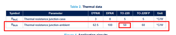
Most vendors specify θJA in a linear regulator datasheet, for example for the case of our L7805CV-DG, θJA is 50 °C/W:

Also, the maximum Tj is 125 °C

So far, we have the following values

PD = 5.9W
θJA = 50 °C/W
TA = 25 (we are going to assume an ambient temperature equal to 25°C)

We are going to use equation (8) to get the permissible dissipated power of our LDO
imagen

So, what's going on here?

Your main problem is your 30V input voltage, the differente Vi - Vo is too high!! You must reduce the input voltage for your l7805
Before connecting the LED's, only your ESP is active, so:

using equation (6)

PD = (30V - 5)(70 mA) = 1.75W this value is less than the value given in (9) for this reason there is no problem when LEDs are not active

not to forget the (unknown) fan

1 Like

I added caps to the 7805.
I originally did not add them as the tutorial I had watched for a large digit driver did not use them either.

For as to why the fan was not included in the schematic, I did not know a fan would make a big difference.
The specs on the fan are: Rated at 5V DC, 0.12A, and 0.6W

Think found out what I did wrong that was causing the over heating, or what I thought was overheating.
I mis-wired the ground for the shift registers and the transistors to the ground pin on the esp32(next to the 3.3v pin) instead of the ground rail on the pcb board. After taking out the esp32 and trying to run just the esp32 it would not detect and would heat up.

I did add the caps as mentioned to the 7805 and also lowered the input voltage to it to 9 volts. So far no overheating issues after replacing the esp32 and the changes to the wiring listed above.

As I continue to test I am going to use a 5v input, single resister and LED on each pin of the ULN2803 to see what segments are turning on before hooking up the full digit segments.

Thank you all for the advice so far.

1 Like

What transistors.
What else is missing from the schematics?
Posting schematics that do not actually represent your circuit is pointless. We can then only guess what you did wrong.

Unfortunately you don't have to have any qualifications or even much experience to make a tutorial.

Check the data sheet for the regulator and look for the "typical circuit".

It will probably draw more current than any other component, including the ESP itself.

And when it starts up, it will probably draw 5x~10x more current than it's normal operating current, just for a fraction of a second while the blades spin up. That can cause brown-outs for the rest of the circuit.

When the fan stops, it will generate a reverse voltage for a fraction of a second while the blades come to a stop. This negative voltage can damage other components in the circuit, like the ESP and other chips. That's why the flyback diode is important. It conducts that negative voltage away so it doesn't reach the other components.

Did you use the values suggested in the data sheet? It's important.

But eventually you will need to increase it again for your led segments, and your problems could return.

I would recommend choosing 12V as a sensible voltage. You would need to re-wire your segments so that you have groups of 3 or 4 LEDs in series, each group having it's own series resistor, and the groups wired in parallel.

I would also recommend replacing your 74hc595+ULN2803 with TPIC6B595. These have a lower voltage drop than ULN chips, as well as making your circuit much simpler. No code changes would be required because the TPIC are very similar to 74hc595 combined with the ULN chip, but better.

True, but 5volt supply and logic only.
The ESP32-S3 then needs additional level shifters.
Leo..

1 Like

This topic was automatically closed 180 days after the last reply. New replies are no longer allowed.