for my home domotics project I need to sense the status of every light in my house.
Thankfully, each light is commanded by a 2ch impulse relay (like this one https://www.findernet.com/en/uk/series/20-series-modular-step-relays-16a/type/type-2022-modular-step-relay-16a/).
My electrical system is composed by 32 relay connected to 32 lights, so I thought to use the spare channel of each relay as feedback signal to my arduino nano.
For this scope I decided to use two input multiplexer, connected as represented in the diagram (I drew only one multiplexer, the second is connected in the same way, just different pins).
My problem is that one of the two multiplexer (always the same) dies after few minutes or hours after switching on or off the lights connected to it.
I think that some induced current form the 220v circuit may be the cause, so I'm here to ask you what kind of protection can I use to prevent this behaviour happening again.
I looked up your relay. You are switching an inductive load with no flyback diode. And you are switching a load whose current requirements exceeds what the 74HC4067 can supply by a couple of orders of magnitude. I cannot express in this forum what I am thinking right now.
Just to be sure that I have explained well how the system is connected.
The input a1/a2 are fed by the 220v pushbutton, the input 1/2 interrupt the phase connected to the lamp and the input 3/4 interrupt the ground connected to the multiplexer.
Should it work if I add the diode?
p.s
don't worry I'm operating safely on a test bench
NO, you are not understanding that the 74HC4067 can not supply the current the 2ch relay draws, that is why the board dies. Even if it could, the relays need 10V not 5V.
SSRs would be one way to go, but they are very expensive. Please test with a remote heat sensing device before installing as your risk for fire is HUGE!!!!!
A less expensive approach is just use a logic level MOSFET to turn on the control voltage for the relays.
Whatever you do, you will need a PSU to activate the relays.
NOTE: They do sell devices to do what you want off the shelf probably priced between the SSR and MOSFET.
I think @giampsen is trying to use a spare set of relay of contacts.
@jim-p pointed out this use of the relay is out of spec. It works now, but mightn't always.
That part is easily solved, I think. A hard pullup and voltage divider should make everyone happy. This would mean an additional supply of power > 10 volts and two resistors per channel on the high power side.
The real problem, what is blowing out the multiplexer, remains. I have no idea why one can't use the spare set of relay contacts for whatever purpose.
Only one multiplexer burns out, so. Is there a wiring or lead dress issue? A wiring mistake? Can you post some pictures of the project?
A solution to both issues might be found by using optoisolators on the high power side, switching them with the spare relay contacts and adding to the switching enough voltage and current to be in specification for the relay, at least 10 volts and 10 mA.
yes @alto777 , you got the point.
Each relay has 2 isolated channels, one channel is used to power up the 220v lamp and the other (the spare channel) is used for the low voltage feedback status.
To complete the picture, the relay coil is driven by the 220v AC through a push button.
I don't see any dangerous thing here, except that I must introduce some protection to the input pins of the multiplexer to overcome voltage spikes from the coil actuation or the load inductance.
The optocoupler is a good option, but for the moment the 5v relay channels are working fine, so I prefer to use one supply voltage.
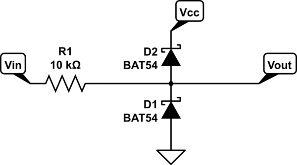
I was thinking to a schottky clamping diode with a resistor in series, something like this:
You must suppress the negative surge from the coil with a flyback diode.
You must use some sort of circuit to provide the necessary current for the coil, because it is in excess of what the multiplexer can provide. On its outputs.
Until you do both those things, your multiplexer will continue to burn out.
That's a sleeper. The relay has a minimum current and voltage switching specification for a reason - it is not guaranteed to switch reliably at lower voltages and currents. I have told you more than I know, always dangerous. I admit to hearing about this relatively recently. The reasoning makes sense.
This might work forever, it might fail sooner than you'd think. It will appear mysterious if you don't at least remember the point.
Cheap tactile switches don't have such a specification, or make it hard to find. Good name brand switches will state it plainly in the data sheet.
Brand name tacts have a fairly low minimum switching current/voltage; big bags of cheap no-names may become problems.
Weigh the cost of failure times the probability of failure against doing a proper circuit now. Obvsly if this was going to the Moon, as we say around here, the equation woukd be different.
I didn't ignore the relay specification, I just ignored the minimum switching load for this reason:
the mechanical action of closing coupled with an actual current flow are required to 'wet' the contact and break through a layer of oxidation that invariably builds up.
That is one reason that small signal relays generally use expensive contact alloys which resist oxidation, but as the phone company found out decades ago, even pure gold contacts can have issues in a high humidity environment. While oxidation doesn't affect the gold contacts, repeated cycles of moist/dry air would deposit an insulating layer.
So the worst case scenario is that the low voltage channel will not be activated, no fire, no smoke, no explosions.
Regarding the induced voltage guess, at the moment is just a wild guess. Unfortunately I don't have an oscilloscope to check this out, I can try with a multimeter.
But I checked all the connections, I also built a second pcb and still the same problem.
More than likely the wrong reason.
The 10V and 10mA requirement suggests there is more to it than just a set of mechanical contacts. You have no idea what is inside that device. Maybe a snubber, some kind of protection circuit that requires that voltage, who knows.
If you want to find out what the problem is then you first need to do things the right way. I would make sure that the voltage is 12V and at least 12mA. Then go from there.
I didn't see anything like anything like that in the datasheet. Is what you speak of common and implicitly understood about this kind of rekay contact?
where you see the same specification with less alarming values.
Or are you saying those numbers for the relay make you think "there is more to it than just a set of mechanical contacts" like "[m]aybe a snubber" that has to be considered when using the relay contacts as intended, that is to say to complete an electrical circuit when closed?
And if that were the case, wouldn't the datasheet want to say something useful about that feature?
So please just say more, some of us are here to learn.