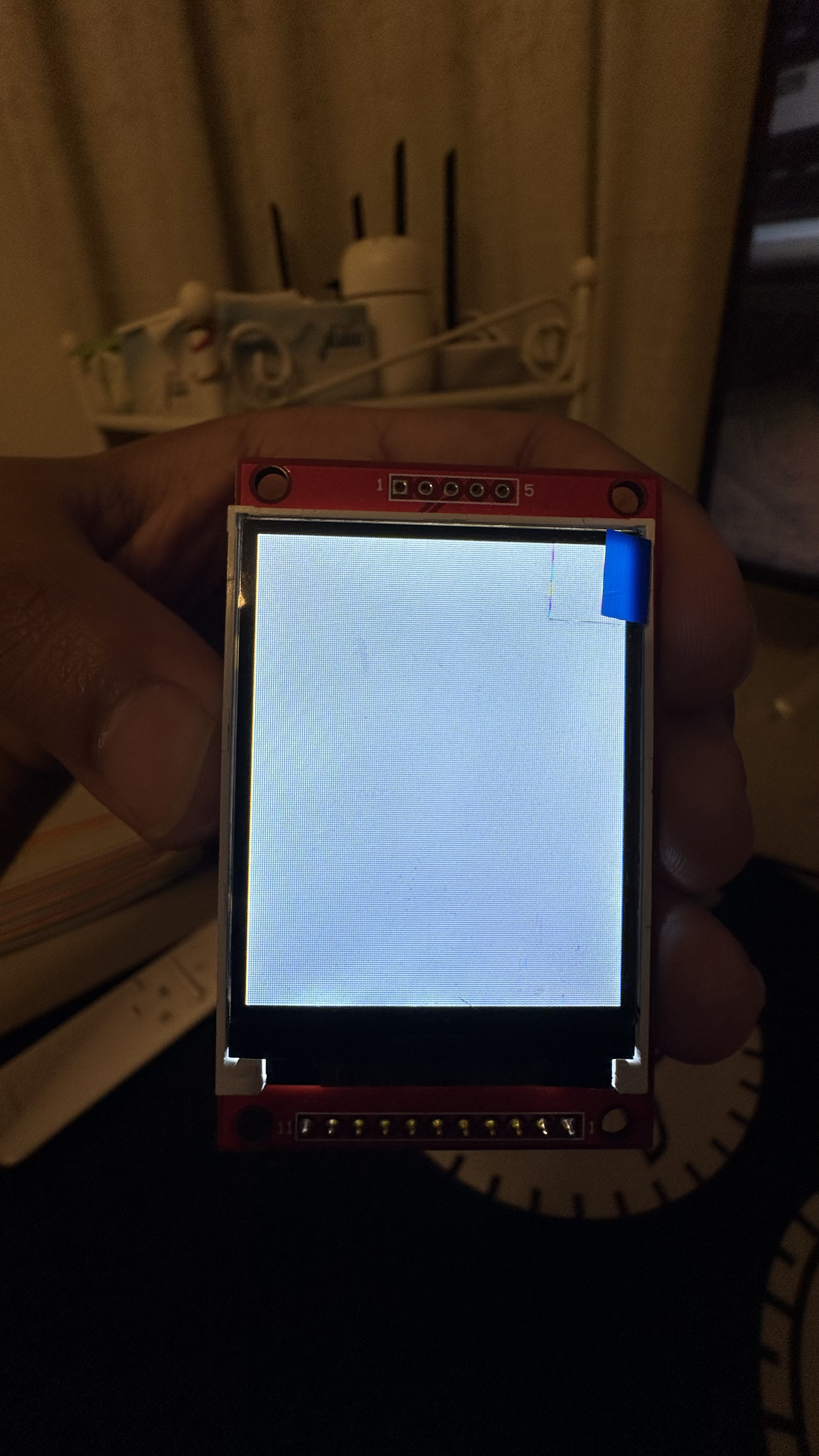
I'm having trouble finding any documentation regarding it, and it will only show me a white screen. How do I proceed and use this display? I'm very lost and worried I won't be able to use this display.
I tried connecting it this way as per chatGPT's suggestion:
Column 1
Column 2
VCC
VCC (3.3V)
GND
GND
GND
Not Connected
NC
Not Connected
NC
Not Connected
LED
VCC (3.3V)
CLK
SCK (SPI Clock, Pin 9)
SDI
MOSI (SPI Data, Pin 8)
RS
4
RST
3
CS
5
I'm using an arduino MKR wifi 1010. Tried running this sample code:
#include <Adafruit_GFX.h>
#include <Adafruit_ST7735.h>
#include <SPI.h>

// Define the pins you're using
#define TFT_CS     5
#define TFT_RST    3
#define TFT_DC     4

// Initialize the display
Adafruit_ST7735 tft = Adafruit_ST7735(TFT_CS, TFT_DC, TFT_RST);

void setup() {
  // Initialize serial communication for debugging
  Serial.begin(9600);

  // Initialize the display
  tft.initR(INITR_BLACKTAB); // You might need to change this depending on your LCD controller
  tft.fillScreen(ST77XX_BLACK);
  tft.setTextColor(ST77XX_WHITE);
  tft.setTextSize(1);
  tft.setCursor(0, 0);
  tft.println("Hello, world!");

  // Print to Serial Monitor for debugging
  Serial.println("LCD initialized");
}

void loop() {
  // You can add code here to update the display
}
Please dont hesitate to ask for additional information. Thank you in advance!
I recommend you get a simple LCD display and learn how they work. Trying to do it without any experience and none of the data is very difficult but you could get lucky.
What LCD module would you recommend for a beginner like me? I made the mistake of assuming all of them would be similar because i didn't have any idea about these.
I actually connected all the wires other than one GND and the NC pins. My reset was connected to 3, i just took the picture before the connections were made.
Am I missing something with respect to the pins on the Arduino MKR? I just trusted ChatGPT's suggestions, but maybe the MKR pins corresponding to the display do not support it.
Check this link , there are many sources for this display. Get it with the backpack (I2C adapter) soldered to it if you do not have the soldering skills. This link should get you several possible sources. https://www.youtube.com/watch?v=xVC0X_PE_XE