DIY Pottery Wheel Arduino Controlled

Hi!

I’m currently in the process of building a pottery wheel for a university project.
First of all: I’m not experienced in electronics, I study product design and am able to get help building & connecting all the electric stuff.

Its not really a robot, but I think controlling the wheel with an Arduino could help, and might make it more future proof & expand possibilites.

I have an old brushed DC motor, 83v, 1kw, geared to 592rpm.
Planning to run it at around 40v (depening on what kind of power supply I can find) to get the RPM down to a usable level.
Pottery wheels usually have a maximum rpm between 250-325.

Now to controlling the RPM & direction:

I need to controll the rpm with a foot pedal, not spring loaded - a volume pedal for an electric guitar would be perfect.
The directions also need to be reversible.
Thats where the Arduino idea comes in.

Does that make sense for you until now, or am I already on a bad path?

Secondly i’d also need to know what hardware I would need for all this.

I would obviously need an Arduino, I suspect a pretty basic one would be enough (as I dont need a lot of sensors etc.)
Then I’d need a DC controller that I can hook up after the PSU and before the motor - correct?

Would this one work: Cytron Single 10- 45V, 40A Brushed DC Motor Controller - RobotShop ?

We’ve had a week of programming the Arduino, and we have somebody that can help with the software side of things.

Im open to any suggetions and ideas, I dont have to use an Arduino - I just havent found another good way to use foot controlls.

Thank you!

Felix
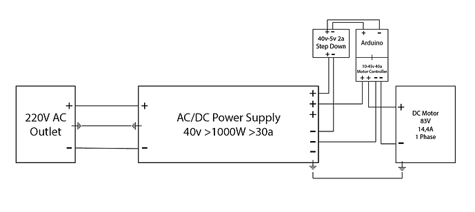
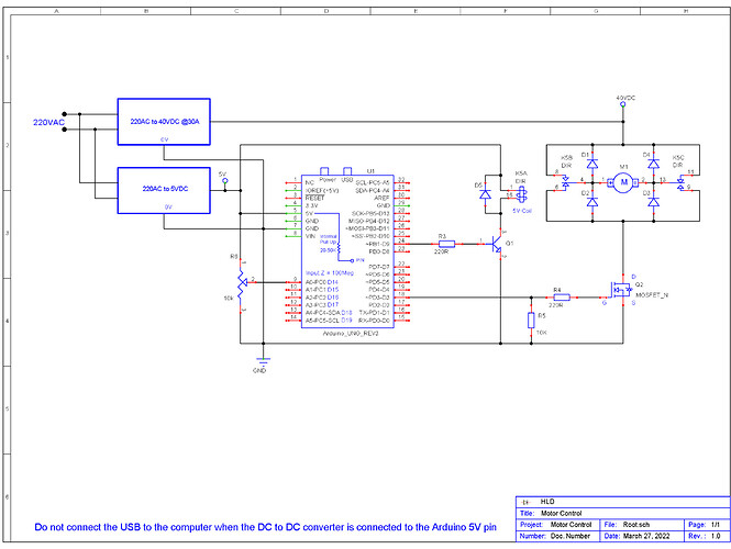
Suggest you start with a block diagram that includes all the items in your project.

Next create a schematic of this diagram.

We can then tear the above apart :wink:

IMO, use a relay to control the direction of rotation.

A simple MOSFET driver should work for PWM control.

I thought working the foot pedal was part and parcel of the whole pottery wheel experience.

Already a bad path! You need to build the physical device first so you know how to connect the motor to the rotating table which has to have thrust bearings to support the weight and to control the tipping of the table.
After that is done, you can determine the torque needed to get the rotation speed of the table to where you want it and also the torque required to accelerate to that speed an maintain it.
That will tell you about the minimum requirements for the motor, etc.

Start tearing it apart :wink:

yes, thats basically what this is about - A well working, quickly responding foot pedal. I'd also like to slowly ramp the motor with the Arduino (because of the added current needed).

I have a pretty good idea as to how I will mount all this stuff, which is very much simplified by directly attaching the motor to the bat.

Its hard to determine the exact torque needed, Im going on existing values used by commercial products. Especially with pottery more torque is usually good, and around 1-1.5hp is what is used in commercial applications.

Be sure to post a video of it working.

Will do, I have time until June :wink:

A motor controller is over kill. :nerd_face:

As mentioned, a DPDT relay for FWD/REV and a logic level MOSFET for PWM speed control will suffice.

It probably is, but it would expand the possibilities - Do you know any arduino compatible motor controllers that would work for this usecase?

I still havent found a foot pedal, and I dont have the knowledge to adapt a pwm controller to an existing one...

We need to know the resistance of the motor to get maximum current.


Pololu might be a place to get them, but 40V at 30A :woozy_face:


FYI
IMHO

EDIT
Had a wire wrong :woozy_face:

Here's are the motor specs

The online calculator states that this motor either has 6.9 ohm (if i enter watts and voltage) or 4.8 (if i enter watts and amps). That doesnt make much sense to me, but i I dont understand this stuff (as you can tell).

I've found a few volume control pedals that use 10k ohm potentiometers - i should be able to wire this one up to one of these cheap chinese motor control boards, as long as the already existing potentiometer is of the same resistance?

Thank you for the diagramm, i think i'll need to read an electronics book before i fully understand it :wink:

Ask if you do not understand :wink:


To be sure, suggest you measure the resistance with a DMM (digital multi meter).

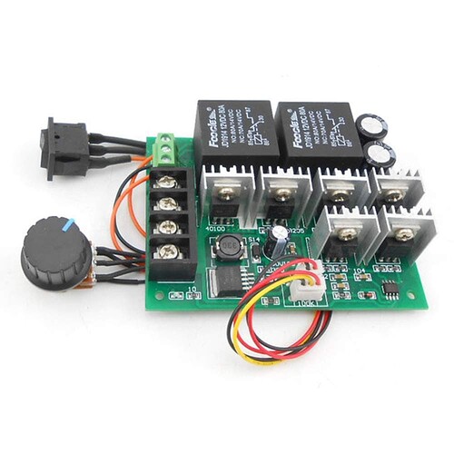
What about just using one of these motor control boards

and just replacing the 100k poti knob with a volume pedal the same resistance?

I wont be able to do that for another 2 weeks, what do we need the maximum current for again?
And also, does it make a difference in the resistance if I run the motor at basically half the voltage?

Thank you.

Would have to read more about the controller.


We need to know the maximum current draw and then add a safety margin.


Let’s say the resistance was 4 ohms.

With a 40VDC supply this says 10 amps will be the max current.


1/2 the voltage will give 1/2 the current.

You will need to try before you buy :wink: .

If the torque is acceptable at 40v then all is fine. :slight_smile:

Its some chinese controller, 9-50v, 40a peak 20a continious - supposedly rated up to 2000w.
It would already have the reverse on it, and atleast on the pcb it says 100k where the poti knob is connected.

This safety margin would be needed for startup etc, as the motor then draws multiple times the current, right?

And we need to calculate that, even though the motor states that its maximum current at 83v is 14.4A?

That i'm not sure about, im finding lots of conflicting information on undervolting dc motors and its effect on current and torque.
Some sites say less voltage doesnt neccessarily mean less current, and that current = torque.

Overall regarding power supply: If I would use a 2kw psu, would the motor draw 2kw or does it just use as much current as it can?

Thank you!

Why are you reinventing the wheel? You can buy DC motor speed controls off the shelf for a lot less effort.

Is AC just straight run to these?

Tbh, i think those werent suggested yet because the voltage is pretty specific. Atleast on the site you linked I only see ones that output too much voltage.

Also I cant figure out what these are called in German, and ordering from america takes a long time (plus import tax).

Im by far not an expert, so the easier the solution is the better. "All" i need is something that drives the motor at acceptable rpm (so around 40v) or i fabricate a gear for it (so that I can run it at full 80v). It needs to be reversable and must have a foot pedal - i have found ones that are basic 10k potiometers.

Google is your friend. He also can translate for English to German if asked nicely.

Unfortunately im unable to find similar PWM controllers that do AC/DC - its also hard to find technical translations, especially if something is just describes as "DC Driver".

Yes, they take AC and output pulsed DC.

I was going to suggest contacting them and telling them what you need and they would be able to point you to a specific model, but if you are only comfortable in German that might be a problem.

KB speed controls are probably used in hundreds of thousands of machines all over the world. They are very well known for what they do.