Driving power mosfet with mcp4725?

hi guys
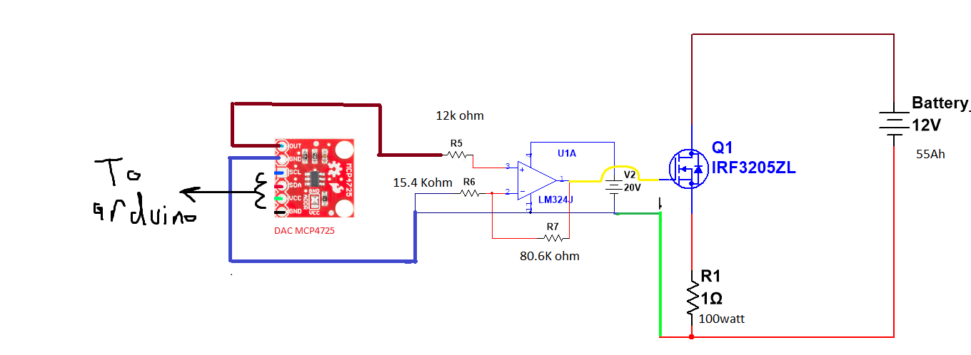
In this circuit I'm trying to drain a battery with a mosfet and resistor.
According to the voltage drop on the gate of the mosfet the current value will changable and it may pass 10Amper.

my question is this circuit okay and can run safely or it may damage the componnets (arduino ,mcp, op_amp), and should I separate it from control circuit , and how this could be done?

Thanks in advance.

Wrong circuit.
Feedback for the opamp should come from the voltage across R1.

Note that a TO-220 package, mounted on a large heatsink, can't dissipate much more than 20watt.
That limits your circuit to 2Amp.
Max power dissipated in the fet is with 6volt across the 1ohm resistor.
6volt * 6Amp = 36 watt.
Leo..

I use mains based light bulbs. For my usage the current is almost constant. A few volts over a 120V lamp, the lamp temperature does not change much hence neither does the current. That load could be shunted with a controllable load, for which I use a BJT, rated at many amps.

Current of that circuit depends on Vgs(th) of the fet, which is unpredictable.
There must be a direct feedback if you want to set an exact current.

I suggest powering the opamp from the 12volt battery, R1 reduced to 0.47ohm (assuming 5volt-logic Arduino), another 0.47ohm between battery(+) and drain, and a resistor the same value as R5 between fet source and opamp -input (no R6, R7).
Leo..

Hi,
This thread is associated with this;

Did you get the circuit to work?

Tom.. :smiley: :+1: :coffee: :australia:

thanks for your answer.

according to the datasheet it can dissipate 200watt.

for the feedback I didn't follow you my friend can you explain a little more how the circuit will be a piece of paper or just a line on picture would be great.

for the set current , in code I will make a while loop if the current is smaller than the set current ,mcp will increase the voltage by 0.1 and the op_amp will multiped by 5 .
and if it's smaller the same idea it will decrease the voltage applied on the mosfet gate.

last question bro , is my circuit is safe to use?

thanks for your answer.
I have replyed to you in the last thread ,I wish you can answer to my question her bro.

wrong mosfet

The ultra-low on-resistance of the SiJH600E and SiJH800E0.65 mΩ and 1.22 mΩ

330W

Hi, @abd222

What exactly are you trying to do?
Are you trying to measure battery performance?

If you want to control a load, why not use PWM?

Tom... :smiley: :+1: :coffee: :australia:

I used mcp to extend the resolution it's 12bit
0->4096

The arduino is 10bit 0->255

In this circuit i will measure the real capacity by draining the battery.

Thanks for your answer .

But what the differance both needs 20 volt to be fully on so why to put x on op_amp

Not sure, is that on datasheet?
mcp4725 - you don't need that if you want only to turn on and off MOSFET

No I don't just to turn on and off i need to pass a value of current that the user deteime it and thats why i need to have a presion with the voltage applied to the mosfet gate.

Yeah it's on datasheet

Thanks for answer .
Yeah i'm trying to measure real capacity of battery so i need to drain it from 100to 0

I'm using mcp to have more resolution
Arduino is 10 bit and mcp is 12 bit

I don't see that

https://www.vishay.com/docs/63073/sijh600e.pdf

what resolution ? Does you load have such stability ?
Do you want to apply different voltages to gate with small steps ? = bad idea

I am going to discharge the battery with resistor and mosfet .
I will control the current flowing with the voltage of the gate of mosfet.

How can i get a constant current ? By using while loop while current is smaller than set current it will increase the voltage on the mosfet gate .

The min threshould voltage 2 volt and the max is 4 volt

So it's not a logic mosfet and it need opamp to drive it

Gate-source threshold voltage VGS(th) 2 - 4 V = 2V delta.
12 bit dac 1 step 4mV x 5 (op amp ) = 20 mV
2V delta/20mV = 100 steps = resolution 6 bit = instead of 4096 steps

wrong , threshould voltage = logic

what resistor, most of them are not stable the resistance is increasing as temperature is rising

LED driver

how you monitor that battery is discharged ?
with accuracy 12 bit

I will measure the battery voltage every 1sec if it's 10.5 volt it's completley discharged.
And iam using ads 1115 16bit for voltage measurements

So what you suggest to drain a battery