Hello everyone,
I am looking to build a battery tester circuit (for a single 18650 2000mAh li-ion cell) capable of subjecting the battery to successive charge - discharge cycles and collect data regarding battery capacity degradation until the battery reaches its EOL(End of life).
Here is a detailed description regarding the hardware setup.
Components
1)ESP32 Devkit V1: primary microcontroller board used to interface sensors, other components and upload measurement data onto thinkspeak.
2)INA219 (current sensor module): measure charging and discharge current.
3)MCP4725 (DAC): provide analog voltage level to opamp at non inverting input, to set the same voltage across load resistor.
4)Micro sd card module: store measurement data as backup.
5)NTC 10k Thermistor: measure battery temperature.
6)BMP280: measure ambient temperature.
7)TP4056 charging module: cheap clone, wires soldered to CE,CHG pin (and then to D32, D33 pins of ESP32) to have the CE pin of IC be low once battery voltage is 4.2v and charge current reaches 100mA, and during discharging.
8)LM358 opamp,IRL540N OR IRLZ44N logic level Mosfet, load resistor R1(1 ohm): form the constant current load part of the battery tester circuit, used to discharge the battery at a constant rate (1a or 2a or 4a, for 3 different boards respectively)
-gate of mosfet driven by output of op-amp.
-drain of mosfet connected to battery +.
-source connected to one end of resistor R1, same point connects to inverting input of op-amp.
power supply to op-amp would ideally be 5v.
Methodology:
start with discharge cycle, discharge till battery voltage reaches 2.75v.
-Then start with a charge cycle to charge the battery to 4.2v
-next, discharge the battery at a constant rate.
-repeat this until battery reaches end of life (70% of rated capacity).This whole process might take somewhere around 2 months for the battery to reach EOL.
-switch between charging and discharging mode either by
1)asserting EN pin of tp4056 ic "low" when voltage reaches 4.2v and charge current 100ma. Also keep it low during discharge cycle.
2)using a relay to control power input to charger.
Meanwhile, during the charge and discharge cycles collect the following data.
- charge and discharge current.
- battery voltage
- battery temperature
- ambient temperature
- cycle count
- capacity.
Now, I am having some trouble with the constant current load /discharger part of the battery tester circuit.
The voltage across the load resistor does not match the expected voltage as set by the DAC (in this case 1v). Instead I only see about 0.6 to 0.7v across the load resistor. This was while only supplying 5v to the power rails of the op-amp.
Increasing the op-amp supply voltage to about 6.38v yields about 0.98v to 1v across the load resistor(for a 1ohm resistor, yielding a discharge current of around 1A). That said, this voltage across the load resistor seems to vary a lot as the mosfet seems to get hotter (provided I had put in only a small heatsink).
I think this might be because the lm358 is not a rail to rail output type op-amp, and a possible solution might be to increase the op-amp supply voltage. But I wish to power the entire battery tester circuit using a 5v,3A power adapter and not use any other buck-boost convertors (mostly to reduce circuit area) to provide higher supply voltages to the op-amp.
So can anyone please help me troubleshoot this issue and get a stable DC voltage across the load resistor (as per the voltage given by DAC to the op-amp), resulting in a current constant current across the resistor. Also any suggestions on suitable replacements for the lm358 op-amp, irlz44n mosfet that might help solve the issue.
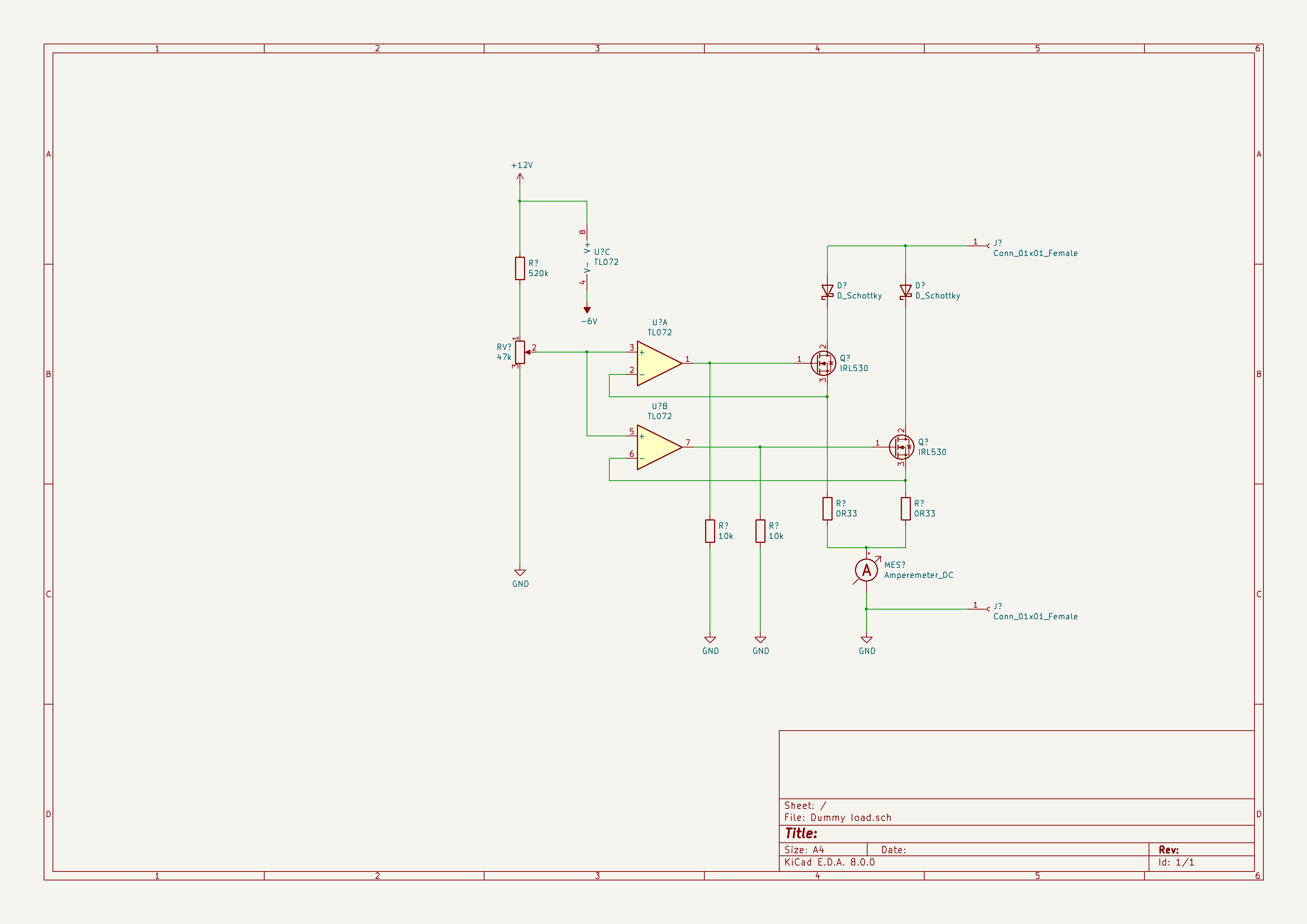
Here is the schematic-
Schematic_18650_testbench_2024-12-22.pdf (92.0 KB)