/*
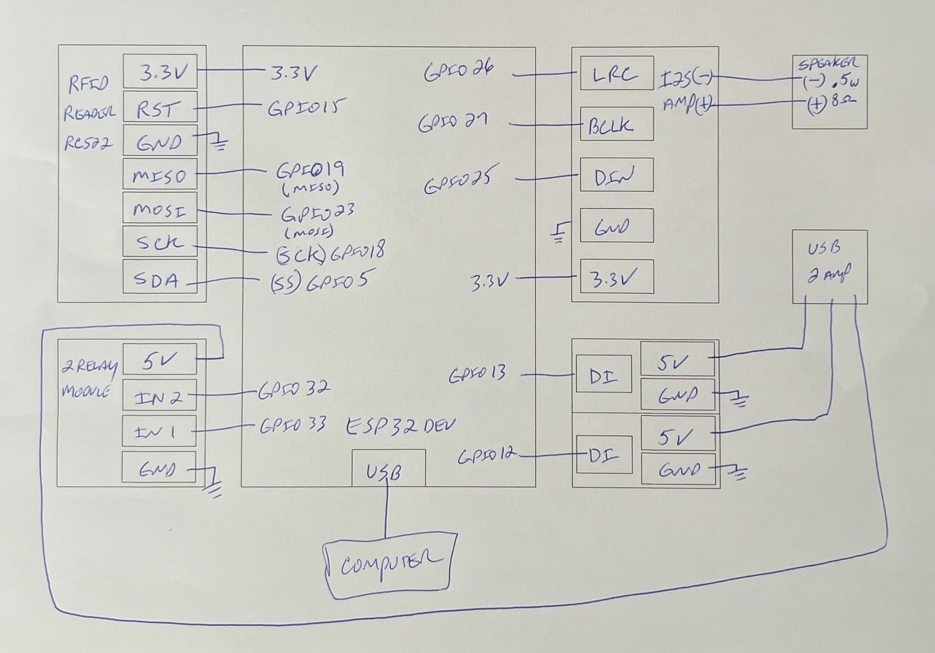
* For more detail (instruction and wiring diagram), visit https://esp32io.com/tutorials/esp32-rfid-nfc-door-lock-system
*/
#include <SPI.h>
#include <MFRC522.h>
#include <Adafruit_NeoPixel.h>
#include "AudioGeneratorAAC.h"
#include "AudioOutputI2S.h"
#include "AudioFileSourcePROGMEM.h"
#include "foolishaac.h"
#define SS_PIN 5 // ESP32 pin GPIO5
#define RST_PIN 15 // ESP32 pin GPIO15
#define RELAY_PIN1 32 // ESP32 pin GPIO32 connects to relay1
#define RELAY_PIN2 33 // ESP32 pin GPIO33 connects to relay2
#define PIN_WS2812B1 13 // The ESP32 pin GPIO13 connected to WS2812B
#define NUM_PIXELS1 12 // The number of LEDs (pixels) on WS2812B LED strip
#define PIN_WS2812B2 12 // The ESP32 pin GPIO12 connected to WS2812B
#define NUM_PIXELS2 12 // The number of LEDs (pixels) on WS2812B LED strip
Adafruit_NeoPixel strip1 = Adafruit_NeoPixel(NUM_PIXELS1, PIN_WS2812B1, NEO_GRB + NEO_KHZ800);
Adafruit_NeoPixel strip2 = Adafruit_NeoPixel(NUM_PIXELS2, PIN_WS2812B2, NEO_GRB + NEO_KHZ800);
AudioFileSourcePROGMEM *in;
AudioGeneratorAAC *aac;
AudioOutputI2S *out;
MFRC522 rfid(SS_PIN, RST_PIN);
byte keyTagUID1[7] = {0x05, 0x2C, 0x7A, 0xD2, 0xC2, 0x42, 0x84};
byte keyTagUID2[7] = {0x02, 0x20, 0x38, 0xAC, 0x4B, 0x54, 0x87};
byte keyTagUID3[7] = {0xFF, 0xFF, 0xFF, 0xFF, 0xFF, 0xFF, 0xFF};
byte keyTagUID4[7] = {0xFF, 0xFF, 0xFF, 0xFF, 0xFF, 0xFF, 0xFF};
byte keyTagUID5[7] = {0xFF, 0xFF, 0xFF, 0xFF, 0xFF, 0xFF, 0xFF};
byte keyTagUID6[7] = {0xFF, 0xFF, 0xFF, 0xFF, 0xFF, 0xFF, 0xFF};
void setup() {
Serial.begin(115200);
SPI.begin(); // init SPI bus
rfid.PCD_Init(); // init MFRC522
pinMode(RELAY_PIN1, OUTPUT); // initialize pin as an output.
digitalWrite(RELAY_PIN1, HIGH); // lock the door
pinMode(RELAY_PIN2, OUTPUT); // initialize pin as an output.
digitalWrite(RELAY_PIN2, HIGH); // lock the door
Serial.println("Tap an RFID/NFC tag on the RFID-RC522 reader");
strip1.begin(); // initialize WS2812B strip object (REQUIRED)
strip1.setBrightness(30); // a value from 0 to 255
strip2.begin(); // initialize WS2812B strip object (REQUIRED)
strip2.setBrightness(30); // a value from 0 to 255
}
void loop() {
if (rfid.PICC_IsNewCardPresent()) { // new tag is available
if (rfid.PICC_ReadCardSerial()) { // NUID has been readed
MFRC522::PICC_Type piccType = rfid.PICC_GetType(rfid.uid.sak);
if (rfid.uid.uidByte[0] == keyTagUID1[0] &&
rfid.uid.uidByte[1] == keyTagUID1[1] &&
rfid.uid.uidByte[2] == keyTagUID1[2] &&
rfid.uid.uidByte[3] == keyTagUID1[3] &&
rfid.uid.uidByte[4] == keyTagUID1[4] &&
rfid.uid.uidByte[5] == keyTagUID1[5] &&
rfid.uid.uidByte[6] == keyTagUID1[6] ) {
Serial.println("Access granted GREY");
// turn on all pixels to green at the same time for two seconds
for (int pixel = 0; pixel < NUM_PIXELS1; pixel++) { // for each pixel
strip1.setPixelColor(pixel, strip1.Color(0, 255, 0)); // it only takes effect if pixels.show() is called
in = new AudioFileSourcePROGMEM(foolishaac, sizeof(foolishaac));
aac = new AudioGeneratorAAC();
out = new AudioOutputI2S();
out -> SetGain(0.5);
out -> SetPinout(27,26,25);
aac->begin(in, out);
}
strip1.show(); // update to the WS2812B Led Strip
delay(1000); // 1 second on time
// turn off all pixels for one seconds
strip1.clear();
strip1.show(); // update to the WS2812B Led Strip
digitalWrite(RELAY_PIN1, LOW); // unlock the door for 2 seconds
delay(2000);
digitalWrite(RELAY_PIN1, HIGH); // lock the door
}
else
if (rfid.uid.uidByte[0] == keyTagUID2[0] &&
rfid.uid.uidByte[1] == keyTagUID2[1] &&
rfid.uid.uidByte[2] == keyTagUID2[2] &&
rfid.uid.uidByte[3] == keyTagUID2[3] &&
rfid.uid.uidByte[4] == keyTagUID2[4] &&
rfid.uid.uidByte[5] == keyTagUID2[5] &&
rfid.uid.uidByte[6] == keyTagUID2[6] ) {
// turn on all pixels to green at the same time for two seconds
for (int pixel = 0; pixel < NUM_PIXELS2; pixel++) { // for each pixel
strip2.setPixelColor(pixel, strip2.Color(0, 255, 0)); // it only takes effect if pixels.show() is called
}
strip2.show(); // update to the WS2812B Led Strip
delay(1000); // 1 second on time
// turn off all pixels for one seconds
strip2.clear();
strip2.show(); // update to the WS2812B Led Strip
Serial.println("Access granted PINK");
digitalWrite(RELAY_PIN2, LOW); // unlock the door for 2 seconds
delay(2000);
digitalWrite(RELAY_PIN2, HIGH); // lock the door
}
else
if (rfid.uid.uidByte[0] == keyTagUID3[0] &&
rfid.uid.uidByte[1] == keyTagUID3[1] &&
rfid.uid.uidByte[2] == keyTagUID3[2] &&
rfid.uid.uidByte[3] == keyTagUID3[3] &&
rfid.uid.uidByte[4] == keyTagUID3[4] &&
rfid.uid.uidByte[5] == keyTagUID3[5] &&
rfid.uid.uidByte[6] == keyTagUID3[6] ) {
Serial.println("Access granted ULY BLACK");
// turn on all pixels to green at the same time for two seconds
for (int pixel = 0; pixel < NUM_PIXELS1; pixel++) { // for each pixel
strip1.setPixelColor(pixel, strip1.Color(0, 255, 0)); // it only takes effect if pixels.show() is called
}
strip1.show(); // update to the WS2812B Led Strip
delay(1000); // 1 second on time
// turn off all pixels for one seconds
strip1.clear();
strip1.show(); // update to the WS2812B Led Strip
digitalWrite(RELAY_PIN1, LOW); // unlock the door for 2 seconds
delay(2000);
digitalWrite(RELAY_PIN1, HIGH); // lock the door
}
else
if (rfid.uid.uidByte[0] == keyTagUID4[0] &&
rfid.uid.uidByte[1] == keyTagUID4[1] &&
rfid.uid.uidByte[2] == keyTagUID4[2] &&
rfid.uid.uidByte[3] == keyTagUID4[3] &&
rfid.uid.uidByte[4] == keyTagUID4[4] &&
rfid.uid.uidByte[5] == keyTagUID4[5] &&
rfid.uid.uidByte[6] == keyTagUID4[6] ) {
// turn on all pixels to green at the same time for two seconds
for (int pixel = 0; pixel < NUM_PIXELS2; pixel++) { // for each pixel
strip2.setPixelColor(pixel, strip2.Color(0, 255, 0)); // it only takes effect if pixels.show() is called
}
strip2.show(); // update to the WS2812B Led Strip
delay(1000); // 1 second on time
// turn off all pixels for one seconds
strip2.clear();
strip2.show(); // update to the WS2812B Led Strip
Serial.println("Access granted MAGENTA");
digitalWrite(RELAY_PIN1, LOW); // unlock the door for 2 seconds
delay(2000);
digitalWrite(RELAY_PIN1, HIGH); // lock the door
}
else
if (rfid.uid.uidByte[0] == keyTagUID5[0] &&
rfid.uid.uidByte[1] == keyTagUID5[1] &&
rfid.uid.uidByte[2] == keyTagUID5[2] &&
rfid.uid.uidByte[3] == keyTagUID5[3] &&
rfid.uid.uidByte[4] == keyTagUID5[4] &&
rfid.uid.uidByte[5] == keyTagUID5[5] &&
rfid.uid.uidByte[6] == keyTagUID5[6] ) {
// turn on all pixels to green at the same time for two seconds
for (int pixel = 0; pixel < NUM_PIXELS2; pixel++) { // for each pixel
strip2.setPixelColor(pixel, strip2.Color(0, 255, 0)); // it only takes effect if pixels.show() is called
}
strip2.show(); // update to the WS2812B Led Strip
delay(1000); // 1 second on time
// turn off all pixels for one seconds
strip2.clear();
strip2.show(); // update to the WS2812B Led Strip
Serial.println("Access granted BLUE");
digitalWrite(RELAY_PIN2, LOW); // unlock the door for 2 seconds
delay(2000);
digitalWrite(RELAY_PIN2, HIGH); // lock the door
}
else
if (rfid.uid.uidByte[0] == keyTagUID6[0] &&
rfid.uid.uidByte[1] == keyTagUID6[1] &&
rfid.uid.uidByte[2] == keyTagUID6[2] &&
rfid.uid.uidByte[3] == keyTagUID6[3] &&
rfid.uid.uidByte[4] == keyTagUID6[4] &&
rfid.uid.uidByte[5] == keyTagUID6[5] &&
rfid.uid.uidByte[6] == keyTagUID6[6] ) {
// turn on all pixels to green at the same time for two seconds
for (int pixel = 0; pixel < NUM_PIXELS2; pixel++) { // for each pixel
strip2.setPixelColor(pixel, strip2.Color(0, 255, 0)); // it only takes effect if pixels.show() is called
}
strip2.show(); // update to the WS2812B Led Strip
delay(1000); // 1 second on time
// turn off all pixels for one seconds
strip2.clear();
strip2.show(); // update to the WS2812B Led Strip
Serial.println("Access granted PURPLE");
digitalWrite(RELAY_PIN2, LOW); // unlock the door for 2 seconds
delay(2000);
digitalWrite(RELAY_PIN2, HIGH); // lock the door
}
else
{
// turn on all pixels to red at the same time for two seconds
for (int pixel = 0; pixel < NUM_PIXELS1; pixel++) { // for each pixel
strip1.setPixelColor(pixel, strip1.Color(255, 0, 0)); // it only takes effect if pixels.show() is called
}
for (int pixel = 0; pixel < NUM_PIXELS2; pixel++) { // for each pixel
strip2.setPixelColor(pixel, strip2.Color(255, 0, 0)); // it only takes effect if pixels.show() is called
}
strip1.show(); // update to the WS2812B Led Strip
strip2.show(); // update to the WS2812B Led Strip
delay(1000); // 1 second on time
// turn off all pixels for one seconds
strip1.clear();
strip1.show(); // update to the WS2812B Led Strip
strip2.clear();
strip2.show(); // update to the WS2812B Led Strip
Serial.print("Access denied, UID:");
for (int i = 0; i < rfid.uid.size; i++) {
Serial.print(rfid.uid.uidByte[i] < 0x10 ? " 0" : " ");
Serial.print(rfid.uid.uidByte[i], HEX);
}
Serial.println();
}
rfid.PICC_HaltA(); // halt PICC
rfid.PCD_StopCrypto1(); // stop encryption on PCD
}
}
}