Hello,
So i have a UNO R3 + WiFi ATmega328P+ESP8266.
Board Layout
The board has two chips, an ATmega328p chip, and an ESP8266 WIFI module. Both chips can communicate with each other and you as a user can communicate/read/write to one over USB depending on how you set the dip switches.


Dip Switches
Communication mode is set using the dip switches as follows:
ATmega <-> ESP8266 1100000
USB <-> ATmega 0011000
USB <-> ESP8266 0000111 (Update firmware or sketch)
USB <-> ESP8266 0000110
All independent 0000000
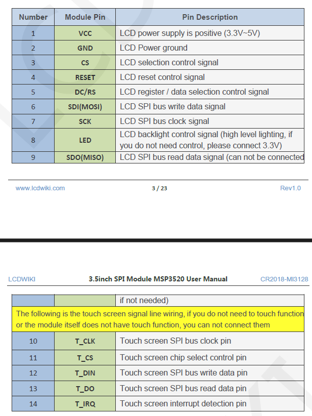
And I wanted to connect the ESP8266 in the board with a 3.5inch SPI Module ILI9488 Touch Screen LCD (320*480) as i want to make an interactive display i can connect to an app on my phone i created using the wifi module.

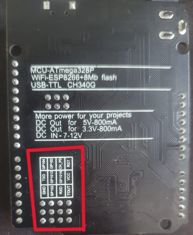
The issue I'm facing is, the ESP module in my board has only 12 header pins and only 5 of them are GPIO pins as seen in the image below.
Now there are 2 problems im facing.
1st - I need a minimum of 6 GPIO pins to connect the LCD to operate it without the touch screen : CS, RST, DC/RS, SDI(MOSI), SCK, SDO(MISO). And 7 GPIO pins if im using the touch screen.

This is a reference image for using the lcd without touch. (PLEASE IGNORE THE NODEMCU 8266 BOARD IN THE IMAGE AS IM USING A DIFFERENT BOARD.)
Question 1 - Do i need to buy a separate ESP8266 board or is there any way to extend the GPIO pins in my board. Or could i use some pins from the UNO header pins and some pins from the ESP?
NOTE - The ESP 8266 header pins in my board do not even have a VIN port / another 3.3v.
A 3.3v output is important as the LCD works on 3.3v.
Question 2- If I use a Arduino UNO board for the lcd connection which has 5V, would i need to use a Logic Level Converter?
I apologize for my naive questions but this is completely new for me.
Thanks.