The Arduino IDE provides a nice built-in example File > Examples > 07.Display > barGraph (https://www.arduino.cc/en/Tutorial/BuiltInExamples/BarGraph) to simulate a bar graph with 10 LEDs.
Here's how you can complete the example with a 4-digit, 7-segment LED display instead. [Note: For simulating a bar graph, the 4-digit, 7-segment LED display is more challenging to program than 10 LEDs. You should complete the built-in example first before building this "4-digit, 7-segment LED display" version.]
Hardware Required
- Arduino Board (I used UNO)
- 4-digit, 7-segment LED display
- 10K ohm Potentiometer
- 4 220 ohm resistors
- hook-up wires
- breadboard
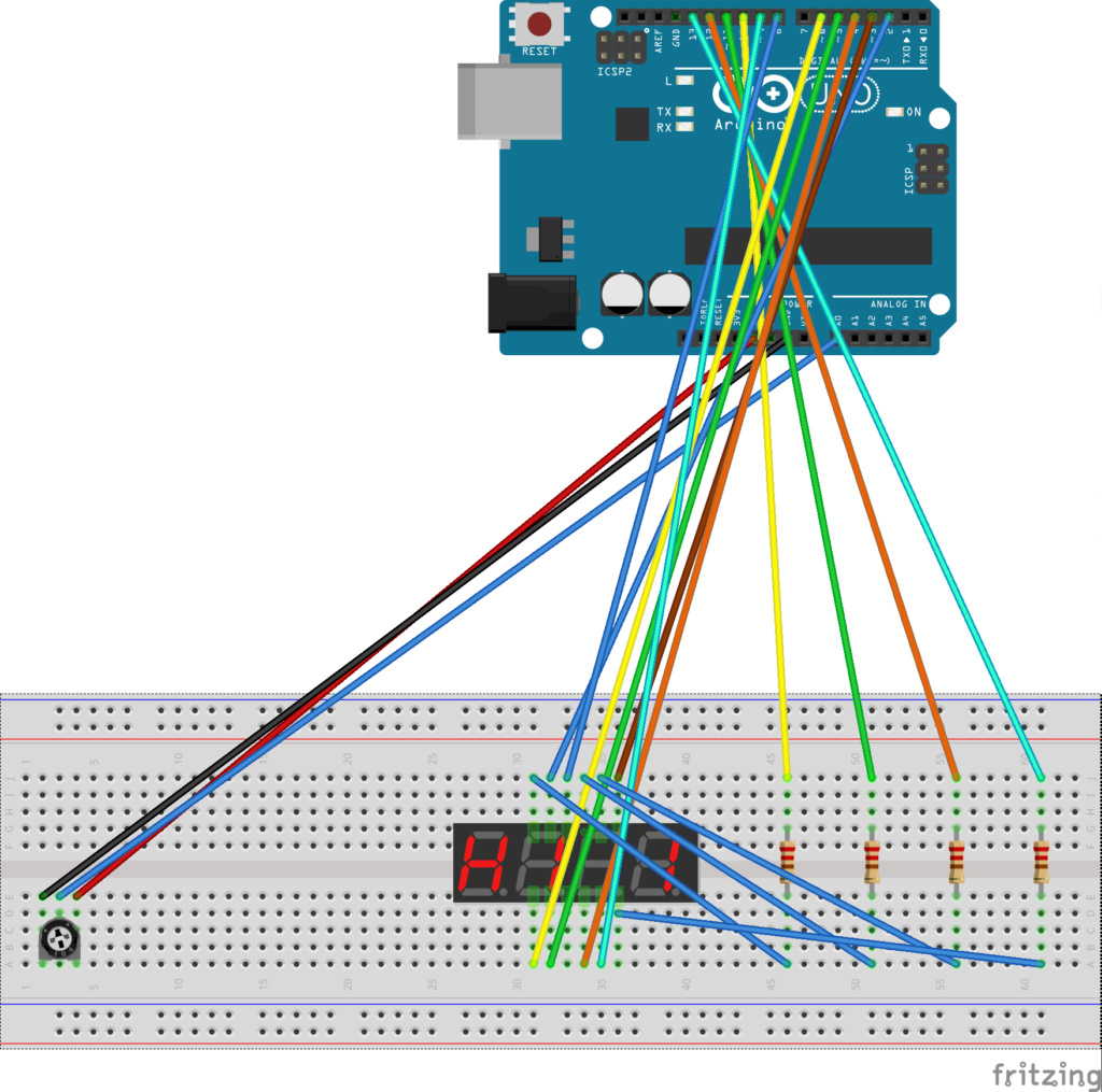
Circuit (to enlarge: https://i30.servimg.com/u/f30/12/91/04/49/bargra13.png)

Schematic (to enlarge: https://i30.servimg.com/u/f30/12/91/04/49/bargra12.png)

Code
Pinouts are detailed in the header comment of this code. Before you build the "4-digit, 7-segment LED display" version of a bar graph simulator, you should read through the code, which is thoroughly documented.
/*
  LED bar graph
*/

/*
  7-Segment LED Display

  Segment   UNO pin     LED pin
  a         2           11
  b         3           7
  c         4           4
  d         5           2
  e         6           1
  decimal   7           3
  f         8           10
  g         9           5

  D1        10          12
  D2        11          9
  D3        12          8
  D4        13          6

*/

// these constants won't change:
const int analogPin = A0;   // the pin that the potentiometer is attached to
const int ledCount = 8;     // the number of vertical lines in the bar graph

void setup() {

  //Set D2-D13 as OUTPUT
  for (int i=2; i<14; i++)
  {
    pinMode(i, OUTPUT);
    digitalWrite(i, HIGH);
  }
}

void draw_digit(int digitPin, bool firstBar, bool secondBar) {

  // turn off all seven segments of the digit and the decimal point (not connected)
  for (int thisPin = 0; thisPin < 8; thisPin++) {
    // the seven segments and the decimal point are connected to UNO pins 2-9
    digitalWrite(thisPin + 2, LOW);
  }

  // for all digits that are part of the bar gragh, the first bar is always lit
  if (firstBar) {
    digitalWrite(6, HIGH);
    digitalWrite(8, HIGH);
  }

  // for all digits that are part of the bar gragh EXCEPT the last digit, the second bar is always lit;
  // for the last digit that is part of the bar graph, the seoond bar may or may not be lit
  if (secondBar) {
    digitalWrite(3, HIGH);
    digitalWrite(4, HIGH);
  }

  // turn on the given digit in the 4-digit LED display
  digitalWrite(digitPin, LOW);
}

void loop() {

  // read the potentiometer
  int sensorReading = analogRead(analogPin);
  // map the potentiometer reading (range 0-1023) to a range from 0 to the number of LEDs
  int ledLevel = map(sensorReading, 0, 1023, 0, ledCount);

  // calculate the number of digits with both bars lit
  int fullDigits = ledLevel / 2;
  // determine if the last digit has both bars lit
  // partialDigit == 0 both bars lit
  // partialDigit == 1 only first bar lit
  int partialDigit = ledLevel % 2;

  // process each digit in the 4-digit LED display
  for (int thisLed = 0; thisLed < 4; thisLed++) {
    // if the digit is part of the bar graph and not the last digit
    if (thisLed + 1 <= fullDigits) {
      // light both bars
      draw_digit(10 + thisLed, true, true);
    // if the digit is the last digit that is part of the bar graph and only the first bar should be lit
    } else if ((thisLed == fullDigits) && (partialDigit == 1)) {
      // light only the first bar
      draw_digit(10 + thisLed, true, false);
    // if the digit in not part of the bar graph
    } else {
      // light nothing in the digit
      draw_digit(10 + thisLed, false, false);
    }
    delay(5);
    // turn off the digit
    // in the 4-digit LED display, only one digit can be lit at a time;
    // however, everything happens so quickly that our eyes think all four
    // digits are lighting simultaneously
    digitalWrite(10 + thisLed, HIGH);
  }

}