xl97:
http://pdfserv.maxim-ic.com/en/ds/MAX7219-MAX7221.pdf
is this what I am supposed to be looking for/at?
Current
DIG 0–DIG 7 Sink Current..............................................500mA
SEG A–G, DP Source Current........................................100mA
No. Those are the absolute maximum the IC can handle. That's not the recommended, nor should it be used as the measuring stick. You do that and the IC will blow before you know it.
xl97:
I saw these lines to:
PARAMETER                             SYMBOL         MIN            TYP         MAX         UNITS
Digit Drive Sink Current              IDIGIT         320                                     mA
Segment Drive Source Current          ISEG           -30           -40         -45           mA
That's what you're after. Not sure why there isn't any data in the typical or max columns but you want to stay within 320mA and the upper limit, which as you found out was 500mA. Personally I would stay within 350-450mA, ideally just around 400mA. At 8 segments, that's 50mA per segment, well above what most digit panels will do.
xl97:
I suppose I could only use 2 of the 3 leads/legs on the 5050's? seems like a bit more work.. but I just keep going back to thinking the 5050 led 'package' fits best for this project.
You could always only use 2 out of 3, or even just one. It just means you won't get as much light out of them, only 1/3 or 2/3 the max the LED can provide.
xl97:
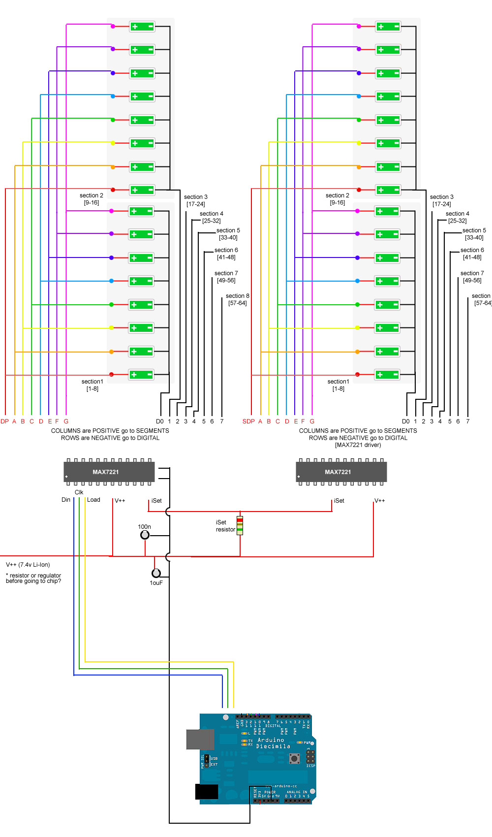
1.) each MAX7221 chip needs a iSET resistor (makes sense, like if you wanted 1 chip to do blue/greens and another to do reds..etc)
2.) each chip needs its OWN set of caps as close to it as possible.
3.) the Dout of main/previous MAX chip goes to Din of the next MAX chip
4.) remaining data lines need to be tapped too (Clk, Load..etc)
anything else I am missing?
Yeah, you need pull-ups at the end of the line. Meaning, your last IC in the chain needs to have its CLK and DATA lines pulled up to avoid reflections.
xl97:
would just bridging 2 of the 3 leds be OK to do? will it pull the 40mA it needs that way by bridging them?
(sorry powering and driving tis correctly has always been a slow going learning curve for me)
Think about that for a minute. If you bridge the two legs, that one LED will be pulling 40mA. Multiply that by the amount of LEDs per IC. If you don't bridge the legs, you'll be using two pins on the IC per LED, so you can only connect 4 of them to the IC. That's 4 LEDS x 2 legs x 20mA ...
xl97:
A.) finding an LED to fit this.. or having someone convince me to stop being a sissy nd just use the 5050 led's but only use 2 of the leds and not all 3
There are single leg white LEDs, you just have to find something that works for you.
xl97:
B.) still un-clear on the PWM side of this... so if anybody DOES have any experience with this, chime in please. 
Someone else chime in please.
xl97:
C.) to be clear (again) I calculate the iSET resistor based on 1 led specs..not a section/total of 8?..right?
You calculate Iset based on one single output. So if the LED pulls 20mA, then that's what you're computing. HOWEVER, if you plan on bridging the legs of a 5050 like you mentioned above, then you need to account for the current capacity when you do that since you essentially have 2 LEDs on one output pin.
xl97:
(a bit confused on when it says it can have up to 8 leds on at any given time.. and the multiplexing that makes it look like leds are on..when they are in fact only blinking/.witching very fast)...
If you put your finger on a hot plate (that's on), how long do you think you can hold it there? Now, if you tap the hot plate really fast with your finger, how long do you think you can keep doing that?
It's the same thing. If you turn on an LED, you start drawing current, and the part starts to heat up. Now, if you flash the LED, not only are you not constantly drawing current and heating up the part, but you're also giving it a chance to cool down when the LED is off, even if it's for a millisecond. The thing is, our eyes can't keep up. Try it for yourself. Write a sketch that blinks an LED, and start at 1 millisecond on, 1 millisecond off. Can you tell when it's on and when it's off? How about 2 millisecond on, 2 millisecond off. How about 5? And 10? At some point you will notice it, but it won't be anywhere near how fast one could flash an LED without you noticing it. So PWM takes advantage of that to keep both the LED as well as the driver cool and not drawing a constant current.
Now, think back to where you saw the 500mA current draw on the MAX. That's peak current, NOT constant current. That means, for a very brief moment, you can pulse 500mA out of the thing without any (minimal) damage. Is it recommended? No because you start to diminish the part's useful life. So with PWM, you could potentially peak it at 500mA ... it's just not recommended.
xl97:
**out of 128 leds.. I might have them ALL on..or maybe just 1.. depending on the animation/code. still just do iSet resistor based on the specs of 1 led right?
Iset gets calculated based on the max current load you'll be putting on a single leg, yes. And you best be pulling the same amount out of all of them too.
By the way, it's Iset, not iSet ... (it's not an Apple device. ) I = current

