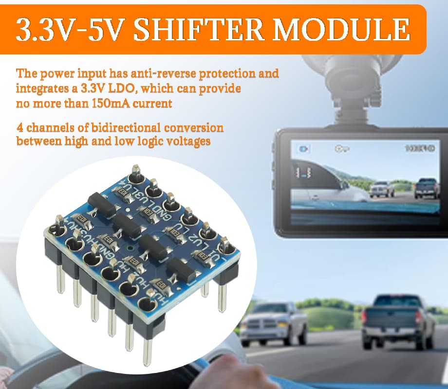
If I test this part stand-alone, in a circuit where there’s nothing but a bench power supply providing 5V and then a (separate) regulator stepping that down to 3.3V, and then I tie the LV side of a channel to either +3.3V or GND, I see the expected output of either 5V or 0V on the HV side. OK, seems great.
However, when I try to actually use this part, and I drive the LV input from a GPIO pin on my RP2040-Zero, alternating between high and low every 3 seconds, I can see, with a volt meter on the LV side, the input going from +3.3V to 0V and back, but the HV output side stays high (+5V) all the time.
What could cause this? I’ve tried it with pull-up resistors (silly, since the part appears to have them included), pull-downs, etc. I just cannot get this thing to function in an actual circuit. What could I possibly be doing wrong? Ideas?
Yep that isn’t a circuit drawing , how it powered ?? Where are you measuring voltages??
Are grounds common between hv and lv ?
What are the output voltages from the micro board in both cases ? Can the 5v pin supply power ?
Are the power connections/0v continuous across the top and bottom ?
“ The Arduino RP2040 Connect operates at 3.3 V, and has the 5V pin (VUSB) disabled by default. This is a safety precaution, as connecting higher voltage signals to the board can damage the hardware.”
The 5V pin will be enabled if the pads marked VUSB are shorted, by soldering them.
Your picture is useless, it indicates how you might put the wires but there is no collation to the actual circuit. Your breadboard could be the cause of your problem, maybe the missing HV connections, or many other things. You will get a much more accurate answer when the annotated schematic is posted.
Here’s the schematic, although please understand: I have disconnected the speed controller, and I’ve disconnected the motor driver. I’m literally just working with 2 buck converters, stepping down from 36VDC to 5.0V and 3.3V, the RP2040-Zero, and the level shifter chip. Nothing else. I’ve removed every variable I can think of.
I’ve tried three different parts of those 12 pin, 4-way level shifters, and none of them worked, and all failed in the same way. Then, on a lark, I tried a TXS0108E that I had on hand… and it worked perfectly right out of the gate. I have another 5 of the 4 channel shifters, but… I’m not sure it’s worth my time. I generally expect that parts mostly work.
I still struggle to understand why those smaller level shifters are failing, especially considering that they’re made of discrete components, and TXS0108E is an IC, but that’s what I’m seeing.
I’m more than a little pissy about this because I have a PCB being fabricated based on the 4 channel, 12-pin parts, but at least I no longer feel like I’m ‘missing something’, since other level shifters are working as expected.
Maybe I just got a bum batch of parts, but what do I know?
The "LDO" stuff is BS.
Do your items look EXACTLY like these, having no solder? (That would guarantee their non-op.)
If you soldered them, perhaps you could demo same.
Yeah, I soldered the pins onto the board myself, and I’m quite confident in my soldering skills (been doing it every few weeks for 35+ years, without issue).
Those modules are designed for I2C level shifting.
The can only pull-down. Pull up is always weak, through the 10k resistors.
The LED in the test of post#3 should have been between HV1 and 5volt, not ground.
The first opto diagram in post#16 therefore won't work, the last one will.
Leo..
You can level logic on 1 line with a diode and a pullup, I bought the cheap 74HC405 in bulk… 16 pins for 6 channels of 5 to 3. I think I got 3 or 4 per $1 pre-COVID.
There is no need to raise 3.3V signals to 5V since 3V is enough to be HIGH to 5V pins.