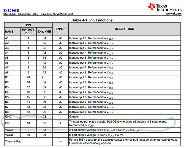
I'm using a HW-221 logic level shifter with my arduino nano to bring 5v down to 3v for a lora module. My issue is that the logic level shifter is reading 0v even when the input is 5v so should be reading 3v. I have tried 2 so I don't think both chips are bad. Have tried connecting the OE pin to 5v, 3.3v, and ground, hasn't fixed anything. Have tried all 3 of those with a 10K resistor in between, also didn't work. Don't know what to do, cant find any more information other than some others have found this chip to be problematic. I am measuring the output from gnd and the A1 socket on the shifter, it is 0v, I have measured the input on B1, it is 5v.
Are you positive that is a level shifter? Here is a link to how to use one, your board looks different.
https://learn.sparkfun.com/tutorials/bi-directional-logic-level-converter-hookup-guide/all
I'm pretty sure it is. This is the amazon listing I bought from.
- Tell us more about what you are trying to accomplish ?
I'm using a LoRa module for remote communication, the data pins on that chip are rated for 3.3v, and the data pins on the arduino nano are 5v, I am using the level shifter to do this. When I finished the original circuit with the LoRa module it wasnt able to initialize, so I started pinning around with my multimeter and found that the level shifter will not give any output voltage at all. So thats where I'm at now.
These work well, and are fully supported by Sparkfun:
Is buying a different product seriously the best solution here? I'd prefer to use the ones I've already bought and would just like to find whats causing this issue.
Yours may work, but I can't figure out from the photographs or the sloppy diagram how you have actually wired it.
If you want help, please take the time to produce and post an informative and complete wiring diagram, with all pins and connections clearly labeled. Hand drawn is preferred.
Solder. Those. Headers.
You're just wasting your time (and potentially damaging the boards) until you do.
Indeed. Good catch, but you had to magnify the image to discover this obviously fatal error.
Will that actually cause this issue? I checked for continuity and all connections seemed good from the multimeter.
Honestly, it's gotten to the point where it's the first thing I check now. I simply cannot fathom how people can think that's going to work.
Solder. Those. Headers.
Stop wasting time.
Oh come on. This is a technical forum, and many contributors here are professionals.
Take the advice and don't come back until you have learned to make clean solder joints. Sparkfun and Adafruit have excellent tutorials.
The board is wired wrong. The two grounds need to be connected, the OE pin should go to the Ground.
This topic was automatically closed 180 days after the last reply. New replies are no longer allowed.


