EPISODE 6: ULTRASONIC RANGING
I will be using an ultrasonic distance sensor (HC-SR04) to measure the distance to an arbitrary object. The display will show the object distance in centimeters and a graphical indicator denoting the proximity status.
I will be using GUI-O IoT (MQTT) connection, but the example can be easily be ported to other connection types.
Software prerequisites:
Components needed:
The entire tutorial is split into various steps. All necessary information is given in each step.
0. DESIGN THE GUI (optional)
The best way to create a GUI layout is to use GUI-O live designer tool.
Note that the Arduino source code already includes the necessary commands, so this step is not needed, unless you want to make some visual adjustments. If you make adjustments, please include the generated ASCII code in the Arduino source code (see section 3. MODIFY AND UPLOAD THE SOURCE CODE).
First, you need to establish a TCP/IP connection between the designer tool and GUI-O application:
- Determine the local IP address of your PC's network interface (WiFi or Ethernet)
- Under Windows, open the command prompt, enter
ipconfig and press Enter
- Under Linux, open the terminal, enter
ifconfig and press Enter
-
Open GUI-O application and open settings menu. Select "Connections -> Ethernet" and create a new device with IP address (determined from 1.) and any port between 49152 - 65535
-
Open GUI-O designer and select "TCP/IP connection" tab. Set the IP address and port. Both values must match the device settings created within the GUI-O application. Click "Start server" button.
-
Within the GUI-O application, tap the created device and wait for successful connection.
-
In the GUI-O designer, select "File -> Load designer file" and load the UltrasonicRanging.gdf design file. Make the desired adjustments, if necessary. Copy / replace the GUI-O commands into the Arduino source code (see section 3. MODIFY AND UPLOAD THE SOURCE CODE).
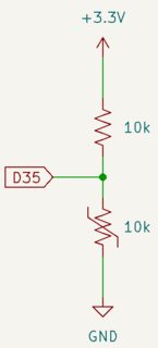
1. CONNECT THE COMPONENTS
Connecting the components is straightforward. The "D32" and "D33" are GPIO pins on ESP32.
2. CREATE A UNIQUE MQTT CHANNEL
Open GUI-O application and navigate to settings menu. Select "Connections -> IoT" and add a new device. After adding the device, note the In and Out token (you can share this tokens e.g., to your e-mail by pressing the "share" button).
Finally, press "Connect" menu entry to establish the connection with the MQTT server.
3. MODIFY AND UPLOAD THE SOURCE CODE
The source code has inline comments, describing the important parts of the code. You can copy the source code from the snippet below, or download it here.
The only thing that needs to be done is to set the ssid and password of your router and the unique In and Out channels that were generated by the GUI-O application (see section 2. CREATE A UNIQUE MQTT CHANNEL).
After setting these values, upload the code to your board (make sure that the correct board and upload port are selected). Reset the board after upload.
/*
 * GUI-O Ultrasonic ranging MQTT example (using ESP32-WROOM-32)
 *
 * Copyright (C) 2022, kl3m3n
 * last updated on 19.11.2022
 *
 * SPDX-License-Identifier: BSD-3-Clause
 */

#include <WiFi.h>
#include <PubSubClient.h>

static const char *ssid = "<ssid>"; // router name
static const char *pass = "<pass>"; // router password

static const char *mqttServer = "mqtt.gui-o.com";   // host name
static const char *mqttUser = "gui-o-mqtt-generic"; // user name
static const char *mqttPass = "lqXeZpv5VJyv0XBT";   // password

// IMPORTANT NOTE: if optional user name was specified when adding a new IoT device,
// the user name should also be included when setting the topics (e.g., "xxxxxxxx-xxxx-xxxx-xxxx-xxxxxxxxxxxx/<user_name>")
static const char *Out = "<Out>"; // GUI-O app publish topic
static const char *In = "<In>";  // GUI-O app subscribe topic

// mqtt client
WiFiClient wiFiClient;
PubSubClient mqttClient(wiFiClient);

// forward declare functions for mqtt messages handling
void mqttCallback(char* topic, byte* message, unsigned int length);
void parseGuioMsg(const String &msg);

char buf[200];

// setup ranging settings
const int triggerPin = 32;
const int echoPin = 33;
// speed of sound in m/us
constexpr float soundSpeedUs = 340.0 / 1000000.0;

// sampling
unsigned long startTimestampMsec, currentTimestampMsec;
const unsigned long readIntervalMsec = 250; // milliseconds

void setup() {
  // debug output
  Serial.begin(115200);

  // setup pins
  pinMode(triggerPin, OUTPUT);
  pinMode(echoPin, INPUT);

  // connect WiFi (keep trying...)
  Serial.print("Connecting to ");
  Serial.println(ssid);

  WiFi.begin(ssid, pass);
  while(WiFi.status() != WL_CONNECTED) {
    Serial.print(".");
    delay(500);
  }

  Serial.println("WiFi connected!");

  // setup mqtt
  mqttClient.setServer(mqttServer, 1883);
  mqttClient.setCallback(mqttCallback);

  startTimestampMsec = millis();
}

void loop() {
  while(!mqttClient.connected()) {
    Serial.println("MQTT connecting...");

    // mqtt client id is the mac address (AABBCCDDEEFF)
    char mqttClientId[15];
    uint8_t mac[6];
    WiFi.macAddress(mac);

    snprintf(mqttClientId, sizeof(mqttClientId), "%02x%02x%02x%02x%02x%02x", mac[0], mac[1], mac[2], mac[3], mac[4], mac[5]);

    if(mqttClient.connect(mqttClientId, mqttUser, mqttPass)) {
      Serial.println("MQTT connected!");
      mqttClient.subscribe(&Out[0]);
    }
    else {
      Serial.print("MQTT connection failed (");
      Serial.print(mqttClient.state());
      Serial.println(")! Retrying...");
      delay(2500);
    }
  }
  mqttClient.loop();

  // get and display temperature
  currentTimestampMsec = millis();

  if(currentTimestampMsec - startTimestampMsec > readIntervalMsec) {
    // pull low, just in case...
    digitalWrite(triggerPin, LOW);
    delayMicroseconds(2);
    // output high level to trigger pin for a short duration
    digitalWrite(triggerPin, HIGH);
    delayMicroseconds(10); // as per datasheet
    digitalWrite(triggerPin, LOW);

    // get distance in cm
    unsigned long pingTime = pulseIn(echoPin, HIGH); //, pingTimeout);
    const float distance = (static_cast<float>(pingTime) * soundSpeedUs * 0.5) * 100.0;

    auto pubBuf = []() { mqttClient.publish(&In[0], &buf[0]); };

    // update distance indicator (keeping implementation simple, though not very readable...)
    // too close
    if(distance < 20.0) {
      snprintf(buf, sizeof(buf), "@dist TXT:\"%.1f cm\" FGC:#FF0000\r\n", distance);
      pubBuf();
      //
      snprintf(buf, sizeof(buf), "@distInd IDXC:\"0:#00FF00,1:#00FF00,2:#FFA500,3:#FFA500,4:#FF0000\"\r\n");
      pubBuf();
    }
    // very close
    else if(distance < 30.0) {
      snprintf(buf, sizeof(buf), "@dist TXT:\"%.1f cm\" FGC:#FFA500\r\n", distance);
      pubBuf();
      //
      snprintf(buf, sizeof(buf), "@distInd IDXC:\"0:#00FF00,1:#00FF00,2:#FFA500,3:#FFA500,4:#D3D3D3\"\r\n");
      pubBuf();
    }
    // close
    else if(distance < 50.0) {
      snprintf(buf, sizeof(buf), "@dist TXT:\"%.1f cm\" FGC:#FFA500\r\n", distance);
      pubBuf();
      //
      snprintf(buf, sizeof(buf), "@distInd IDXC:\"0:#00FF00,1:#00FF00,2:#FFA500,3:#D3D3D3,4:#D3D3D3\"\r\n");
      pubBuf();
    }
    // far
    else if(distance < 70.0) {
      snprintf(buf, sizeof(buf), "@dist TXT:\"%.1f cm\" FGC:#00FF00\r\n", distance);
      pubBuf();
      //
      snprintf(buf, sizeof(buf), "@distInd IDXC:\"0:#00FF00,1:#00FF00,2:#D3D3D3,3:#D3D3D3,4:#D3D3D3\"\r\n");
      pubBuf();
    }
    // very far
    else {
      snprintf(buf, sizeof(buf), "@dist TXT:\"%.1f cm\" FGC:#00FF00\r\n", distance);
      pubBuf();
      //
      snprintf(buf, sizeof(buf), "@distInd IDXC:\"0:#00FF00,1:#D3D3D3,2:#D3D3D3,3:#D3D3D3,4:#D3D3D3\"\r\n");
      pubBuf();
    }

    Serial.print("ping time = ");
    Serial.print(pingTime);
    Serial.println(" us");
    Serial.print("distance = ");
    Serial.print(distance);
    Serial.println(" cm\n");

    // reset read interval
    startTimestampMsec = millis();
  }
}

// mqtt callback function
void mqttCallback(char* topic, byte* message, unsigned int length) {
  // build message string
  String msg;
  for(int i = 0; i < length; i++) {
    msg += (char) message[i];
  }
  // parse message string
  parseGuioMsg(msg);
}

void parseGuioMsg(const String &msg) {
  if(msg.startsWith("@init")) {
    Serial.println("GUI-O app is requesting INITIALIZATION!");

    // clear screen and set background
    mqttClient.publish(&In[0], "@cls\r\n");
    mqttClient.publish(&In[0], "@guis BGC:#FFFFFF\r\n");
    delay(100);

    // initialize GUI
    mqttClient.publish(&In[0], "|LB UID:title X:50 Y:20 FSZ:4 FFA:\"font8\" TXT:\"Ultrasonic<br>ranging\"\r\n");
    mqttClient.publish(&In[0], "|RECG UID:distInd X:50 Y:50 W:30 H:20 HIW:0 ROWS:5 COLS:1 SPC:0.5\r\n");
    mqttClient.publish(&In[0], "|LB UID:dist X:50 Y:70 FGC:#4C4C4C FSZ:6 TXT:\"n/a\"\r\n");
    mqttClient.publish(&In[0], "|LB UID:details X:50 Y:90 FSZ:2 TXT:\"GUI-O ultrasonic ranging<br>demonstration by kl3m3n\"\r\n");

    // must send as a new message (minor GUI-O application bug)
    mqttClient.publish(&In[0], "@distInd IDXC:\"0:#D3D3D3,1:#D3D3D3,2:#D3D3D3,3:#D3D3D3,4:#D3D3D3\"\r\n");
  }
}
4. ESTABLISH CONNECTION
Make sure that the GUI-O application is connected to the MQTT server.
Also make sure that the ESP32 board (or other Arduino supported board) is connected to the MQTT server (you can check this by observing the serial debug messages using the Arduino serial monitor).
Press the Initialize button (see image below) from the GUI-O application home screen.
5. THE RESULT
Image below shows the result (screen capture) on my Android device after pressing the "Initialize" button. The bars graphically represent the object proximity based on some predefined intervals (green = far, orange = close, red = collision imminent).
If you have any questions or run into any problems, please let me know!
Best regards,
kl3m3n


")


")
, applies to GUI-O version 1.0.32 and up")