OK, that's pretty straightforward.
By the looks of it you've got, from left to right (looking at the component side):
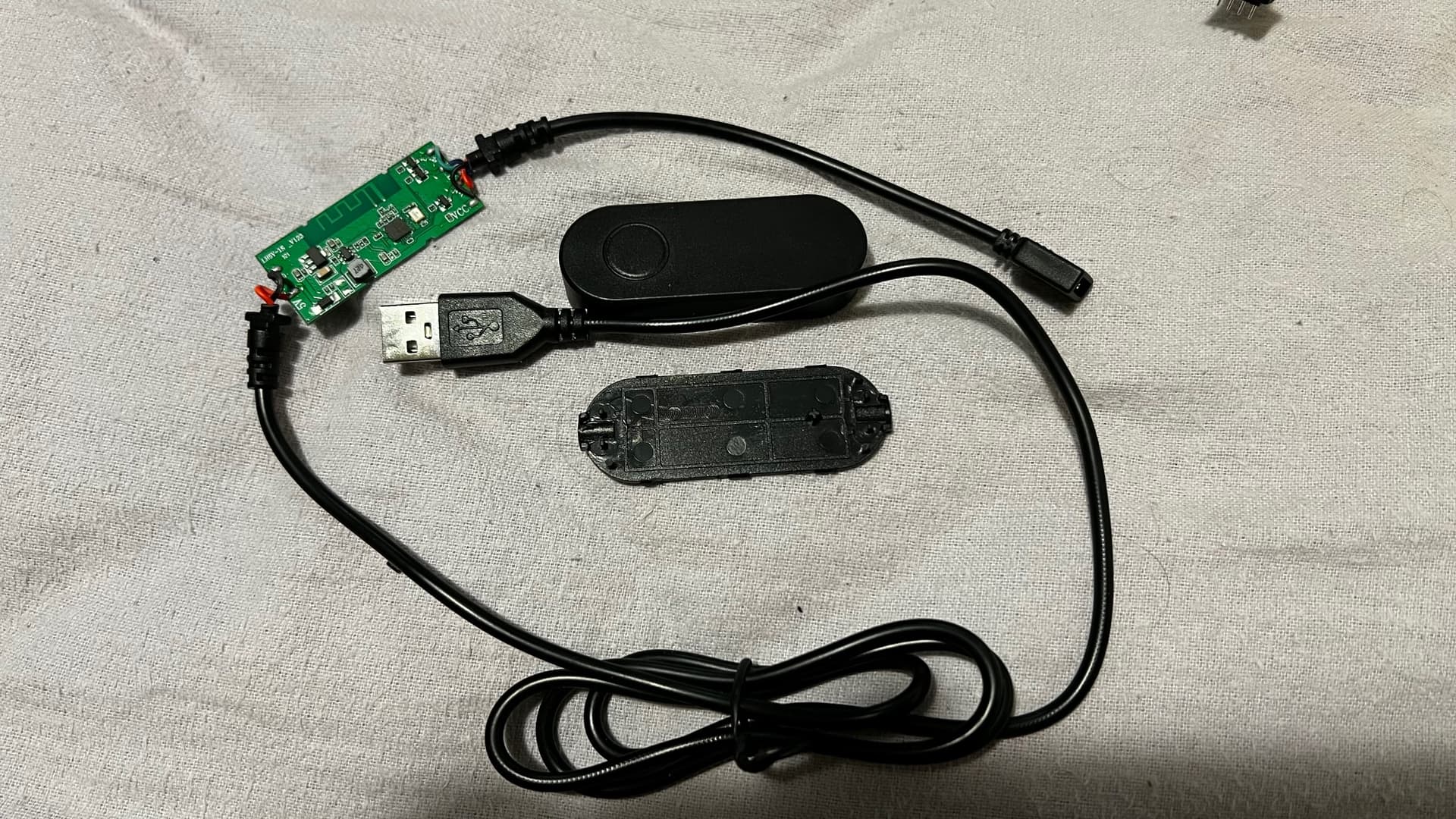
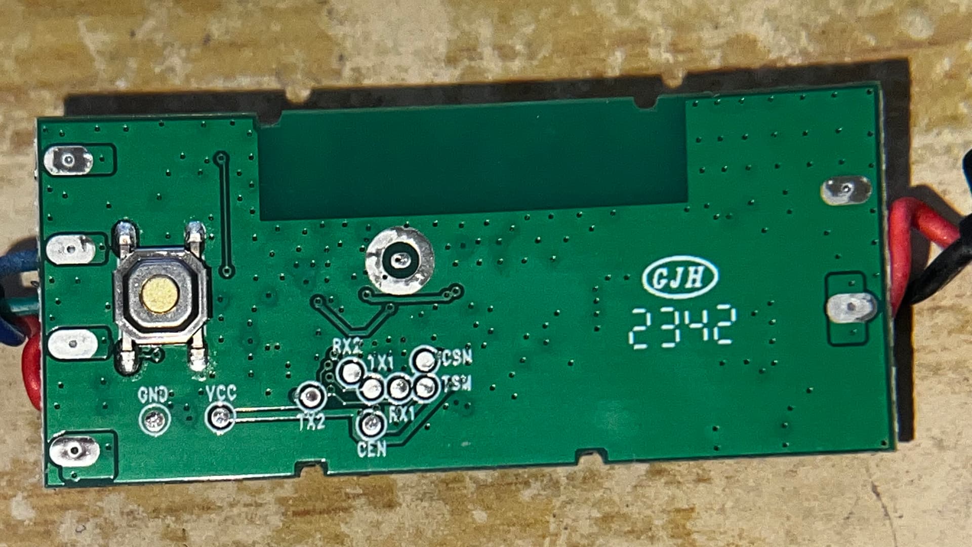
- a 3.3V logic power supply based on the generic AMS1117 linear regulator; this powers the controller.
- An approx. 3V DC-DC buck regulator that brings 5V input down to approx. 3V for the LEDs.
- A controller with integrated WiFi (not PCB antenna); it looks like a 7231N, for which there's a datasheet here: https://www.iottech-corp.com/datasheet/iot/ITM-7231N-BK%20Datasheet_V0.3_20211105.pdf It has WiFi and most/all of the regular peripherals you find on a modern microcontroller.
- Three low-side switching MOSFETs that make the LEDs dim using the PWM output from the controller. (On the backside there's the user input microswitch in this area).
You could easily substitute your own circuit for this one. It might even be possible to re-program the controller with your own software, but this would involve some serious digging into datasheets/reference manuals (which may be only available in Chinese), getting the necessary programming tool (hardware) and toolchain (software) and then working your way to get usable code; I don't think there's an Arduino core for this mode, so you'd have to rely on bare-metal programming. Nice if you're part of the Hackaday crowd, but if you just want to get the job done, just ignore this PCB and substitute your own Arduino-based board.
An intermediate way of hacking this device would be to cut a few traces around the microcontroller and solder your own device to it; you could then keep using the 3.3V and 3V power supplies as well as the switching MOSFETs and the input button. It's doable with a utility knife, a loupe/microscope and a fine-tip soldering iron. Something like an Arduino Pro Micro or an even smaller board may even be made to fit inside the original housing.
Of course you could also simply set the entire controller part (including housing) aside and substitute your own project box.
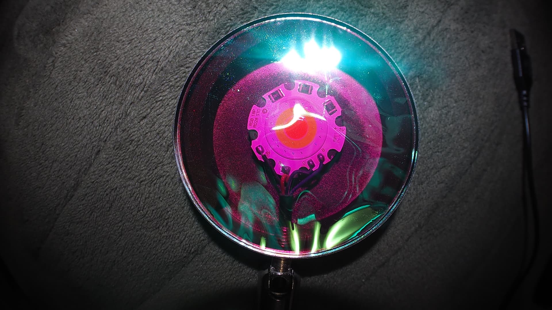
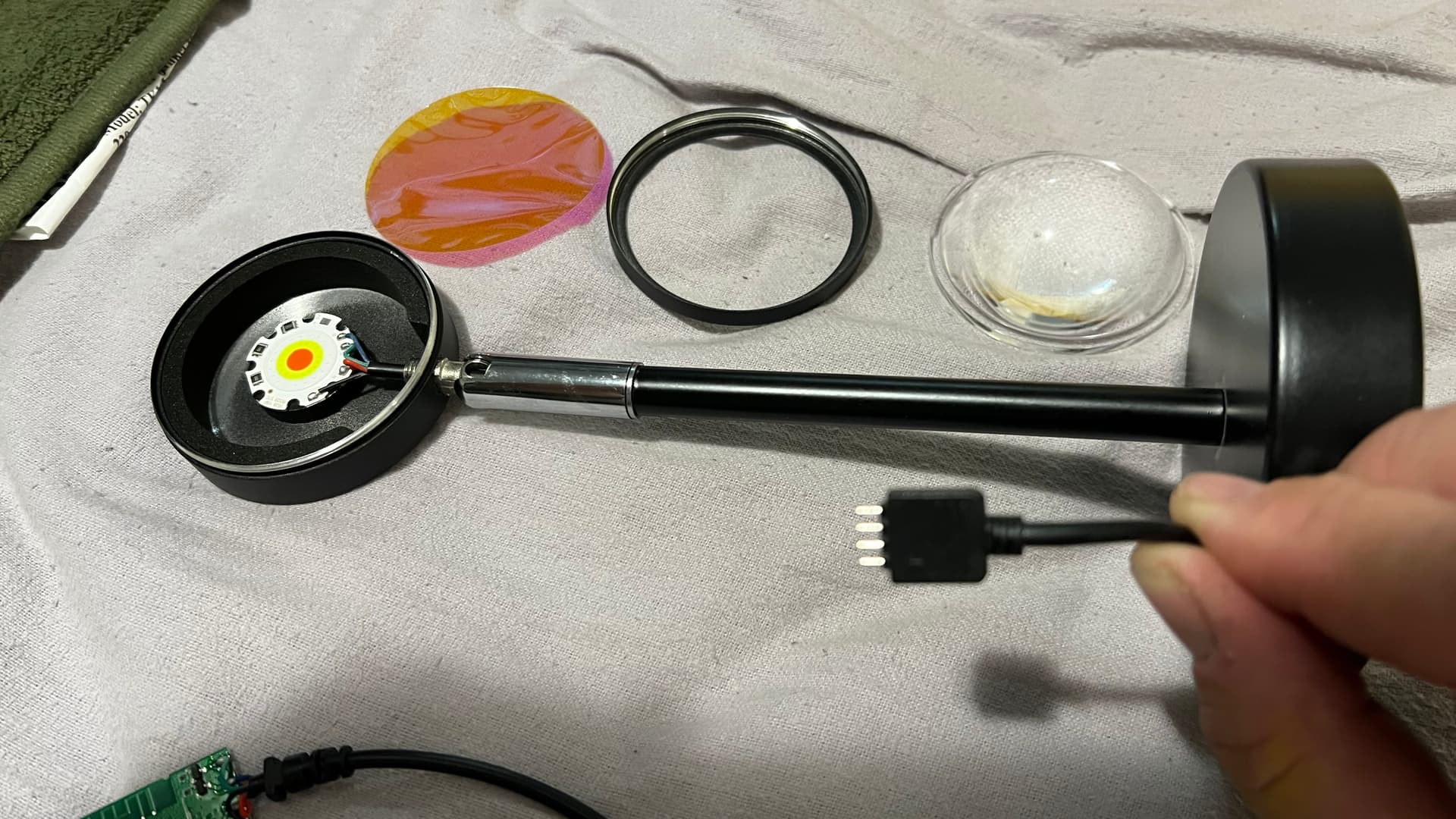
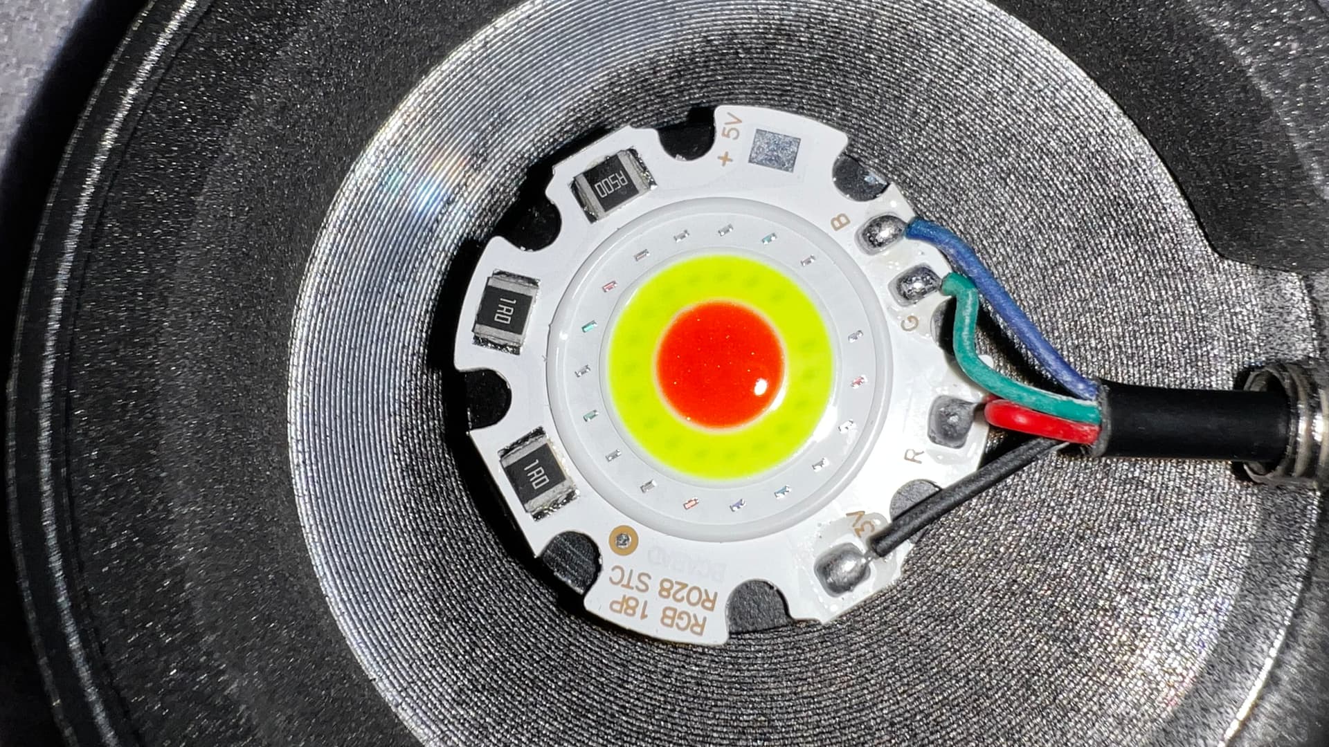
The LED arrangement looks simple enough; apparently you've only got R, G and B LEDs and my guess is that you'll find red in the center, then green in the middle and blue along the outer rim. Note the current limiting resistors of 1Ohm for R+G and 0.5Ohm for B; blue has a higher forward voltage so they used a lower value resistor there. It's all very straightforward. Maximum continuous currents will likely be around 1.2A for all three channels, so 3.6A in total. You need a 3V power supply capable of sourcing at least ca. 5A for this light source (always apply a little safety margin).
The 5V pad on the light source PCB is a little puzzling; you could test with a continuity meter whether it connects to anything. Anyway, you could just ignore it for your application.
Definitely not; that's an aluminum-core PCB so it's a single layer, single-sided PCB. The back is bare aluminum for heat dissipation. The housing probably acts as a heat sink. I bet this thing gets HOT when/if run at full power, which it's likely not supposed to.
No, I actually meant that you could build something like this starting from scratch. But I can see how and why the form factor / physical shape of the light source and its housing might be useful to you, in which case you can indeed substitute your own controller. Note that the lens included looks like a generic COB LED lens that you can buy for around $1 a piece (or less) on AliExpress. It's either a 60 degree or a 120 degree angle type.
When adding your own controller, keep in mind that the heat dissipation of the housing probably is insufficient to run this thing at full power for more than 3 seconds or so. It's likely intended to only be used with all three channels dimmed to some extent. I expect that the light source as shown is capable of dissipating around 3-4W for any extended period of time, so roughly 30% of the power the LED arrangement could do.