Hello everyone! I'm trying to decode the communication protocol between the main controller and the display controller of a CDJ800 MK1. I want to use it as a surface controller over HID, but that's a different story. For now, I want to be able to command the display microcontroller from an Arduino. I have this project as a reference, but it seems too different for the CDJ800MK1.
The first approach that I took was to spy on the default communication using a logic analyzer. I'm not certain about what I'm seeing. it's like an SPI protocol with bit banging. I tried to read the output packets from the display microcontroller using an Arduino snippet, and I'm seeing a lot of packets with the index of a button, but without any coherence in structured messages. I suspect that I might be losing packages.
I tried to unplug the main board and use the Arduino as a master device using SPI, but nothing happened.
The display controller is a M38B79MFH an talks over the IO/3 port.
Any support is welcome. My focus is to create a library to communicate with the device.

Does your logic analyser have any decoders built in? I would imagine that most modern ones can handle UART, SPI & I2C decoders.
The signals do look to be like SPI - SS and CLK stand out. TSOUT and TSIN may be the wrong way round if you don't already know which is which.
I guess you may have found this website: Converting Old CDJ-800s Into Traktor MIDI Controllers - DJ TechTools
What does your LA say the SPI clock speed is?
Thanks for your quick response, markd833. Yes, I had already seen that website before, but the approach there involves controlling the buttons one by one, without an easy way to control the display. Because of this, I prefer to communicate directly with the display controller.
Looking at the controller pinout, I think the TSOUT and TSIN are correct, but I might be confused. I'm connecting TSOUT to SOUT3 (PIN13) and TSIN to SIN (PIN14).
I'm using DsView with this analyzer. With the software's built-in SPI decoder, I haven't found anything coherent (I tried all the options). I've had better results using the Arduino as a spy, as I mentioned before.
I'm not sure if I can read the clock speed with my logic analyzer, but the distance of the clock pulses appears to be 1MHz. Hopefully, you can help me with this.
Ok, so full disclosure ... until you posted, I had no idea what a CDJ800 was. I saw communication protocol and thought i'll have a go!
It looks like DSView has a protocol decoder for SPI. How friendly that is, I don't know.
I've got myself one of the really cheap $20 8ch logic analysers and recently started playing with it using Sigrok Pulseview. I had a quick look and it seems that the DSLogic Plus is supported by Pulseview. Pulseview has a bunch of decoders built in, and it's all free.
However I just read on that page:
New hardware variant received early 2023, enumerates as 2a0e:0030, and uses a different vendor's FPGA. Currently incompatible with sigrok.
Can you upload a screenshot that shows the CLK in more detail - i.e. zoomed in onto one set of clocks where SS is LOW. It needs to show a logic level change on TSOUT and/or TSIN. Maybe we can figure out which SPI mode the protocol is using.
DsView is a fork from Sigrok, and I guess it has the same SPI decoder.

In this second one, the SS line does things that I can't understand.

Looking back at the image from post #1, CLK is high between transmissions. The top image in post #5 shows the CLK rising in the middle of the DATA pulse. I believe that equates to SPI Mode 3.
The LA is correctly decoding that as 128 decimal.
I wonder if the spurious SS transitions are down to a poor LA probe connection?
Umm, I hadn't thought of that. I have 20cm wires soldered to the pins on the PCB, and I'm picking up the signal from these. I'm going to try with shorter wires and see If I get luky.

It's possible that the glitches on SS are an artefact of the software SPI bit banging. It could be that the other device doesn't see them, especially if it too is using a software SPI implementation.
I tried a simple Arduino code to simulate the original wave, disconnecting the main controller, but I'm not able to generate a 1MHz clock. How can I do this? I have an Arduino UNO.
As you can see in the picture, the microcontroller doesn't respond to anything, of course, I checked that it's correctly powered.
#include <Arduino.h>

#define SS_PIN   10
#define MOSI_PIN 11
#define MISO_PIN 12
#define SCK_PIN  13

byte sendData[8] = {254,254,7,0,0,0,0,254};   // Values to be sent
byte slaveData[8];  // for storing the values sent by the slave

void printWord(){
  for (size_t i = 0; i < sizeof(slaveData); i++)
  {
    Serial.print(slaveData[i], DEC);
    Serial.print(" ");
  }
  Serial.println();
}

byte spiTransfer(byte dataToSend) {
  byte dataReceived = 0;

  digitalWrite(SS_PIN, LOW);

  for (int i = 7; i >= 0; i--) {

    digitalWrite(MOSI_PIN, bitRead(dataToSend, i));

    digitalWrite(SCK_PIN, LOW);

    bitWrite(dataReceived, i, digitalRead(MISO_PIN));

    digitalWrite(SCK_PIN, HIGH);
  }

  digitalWrite(SS_PIN, HIGH);  // Desactiva el dispositivo esclavo

  return dataReceived;
}

void setup (void) {
  pinMode(SS_PIN, OUTPUT);
  pinMode(MOSI_PIN, OUTPUT);
  pinMode(MISO_PIN, INPUT);
  pinMode(SCK_PIN, OUTPUT);

  digitalWrite(SS_PIN, HIGH);
  digitalWrite(SCK_PIN, HIGH);

  Serial.begin(9600);

  Serial.println("Lest'sGO!!");
}

void loop (void) {

  for (size_t i = 0; i < sizeof(sendData); i++)
  {
    digitalWrite(SS, LOW); // SS low
    slaveData[i] = spiTransfer(sendData[i]); // data transmission
    digitalWrite(SS, HIGH);       // SS high again
  }
  printWord();
  delayMicroseconds(26);
}

Any particular reason you are not using the actual SPI hardware interface on your UNO?
If you use the hardware interface, then I believe that you can set the clock to 1MHz using the SPISettings function.
Yes, I tried to do it with the hardware SPI without any results. I'm not sure about this, but I think that the default SPI protocol writes a Byte and reads a Byte, and seeing the LA, I thought that I need to write a Bit to read a Bit.
Regardless, I'm testing it now and I'm also not getting anything at 1MHz.
Yes, that is exactly how SPI works. When the master clocks out 1 bit to the slave, at the same time the slave clocks out 1 bit to the master.
That's why when you want to read 4 bytes from an SPI slave device, you have to send (i.e. write/clock out) 4 "dummy" bytes to the slave device.
This from the 328P datasheet:
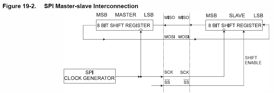
Do you know that you are sending the correct message out? It can be tempting to think so when looking at an LA trace. Does the master device (in this case I guess your UNO) send out the same message continually in order to get a response from the slave device?
Some of your LA traces show activity on the TSOUT trace but the trace in post 10 shows TSOUT high all the time.
Yep when I disconect the main microprocessor the TSOUT is high all the time. In the post 10 you can see the Arduino UNO sending the same 8 byte as the main microprocessor in the startup sequence (It's hard to know, the SPI decoder don't work well with the SS glitches). But the TSOUT not drop (for send 00000000)
EDIT: Seeing that the first Bytes of the TSOUT in the original LA are 128 (the other Bytes are 0 except the last one), I'm beginning to suspect that I'm missing some ping configuration or something, but I can't find it, currently I have everything connected to the main board, except these 4 lines 
EDIT2: Seraching in the manual I find this

Bingo! After checking that pin 18 was LOW, I made a bridge between this pin and 5v. Now the display shows the same as when it was connected to the main display, but the responses seem to be wrong. It's always high and randomly sends a message, but it doesn't seem to have any relation to the buttons pressed.
The next thing I want to try is applying some kind of filter over the SS line for remove the glitches (in the original LA analysis) and decode it to find new messages to send.
The first step is generally the hardest when trying to reuse older hardware. After that, progress tends to be quick. But there's still the chance if a curveball!
Good luck.
Finally! I can communicate with the microcontroller! markd833, you were right, the MISO and the MOSI lines were exchanged. TSOUT corresponds to MOSI, TSIN corresponds to MISO. So now I have other problems. xD I found something similar to a message structure but sometimes it has a 16Byte length and sometimes it's 15Bytes.  Could this problem originate from an error in the SPI configuration and the last bytes are getting lost? Currently, this is the configuration I'm using.
void setup (void) {
  pinMode(SS_PIN, OUTPUT);

  SPI.begin();

  SPI.beginTransaction(SPISettings(2000000, MSBFIRST, SPI_MODE3));

  Serial.begin(115200);

  Serial.println("Lest'sGO!!");
}
Are you referring to the SPI messages between the 2 parts of the original system? It could be that they really are meant to be different lengths, if, for example, there are 2 message formats. I would expect to see some sort of ID - likely in the first byte - that differentiates between the 2 message formats if that were the case.
If you were referring to your own code, the first thought I would have is that maybe SS is going high before the final byte has a chance to exit the hardware. A timing issue could explain why the final byte sometimes makes it out and sometimes doesn't.
Does your LA show activity on MOSI / MISO when SS has gone high?
From what I see, there is only one type of message, which is marked by the first byte as 1. Looking at the Logic Analyzer, I don't find anything suspicious with the SS lines or the clock line. It simply seems like the slave starts a new message before the 16 bytes are transmitted (or sends one more byte). I'm thinking this might be a problem related to the timing between the bytes being sent or something similar. Is this possible?
EDIT:
Are you referring to something like this?

It's possible. I wonder if the slave is expecting to return bytes at a specific rate. If your clock is running slow, I wonder if the slave is getting its timing wrong.
What does your LA say the clock frequency is when using the real hardware compared to your Arduino.