Hello my name is shaffick, i am back again this time with more detail and drawn out piece to show you so you can understand what i am working on. I have been working on a mechanical art piece that uses strong motor cause of the gear parts. This is the small setup.
The motor i used was one, that i had laying around and ended up designing the piece around it, is a CHANCS 555 BRUSHED DC MOTOR 24V 3500RPM HIGH TORQUE
I am going to be controlling 67 of those or i want to controlle 67. So the question part.
How would i do this?
What controller type or driver would i use?
power supply box?
It is going to be plugged in, on an everyday outlet.
Why 24v motor? The gears would be moving arms in some art piece and the other reflector plates that shine different color for a different art piece to make faces or locations. the gear plate piece
Assuming you want to start and stop them you can use a solid state relay. Be sure the relay is rated for your motor or greater.
If they are to be reversed you will need a H-Bridge. I am guessing they will need a few amps, here is a relative inexpensive H-Bridge that should do the job.
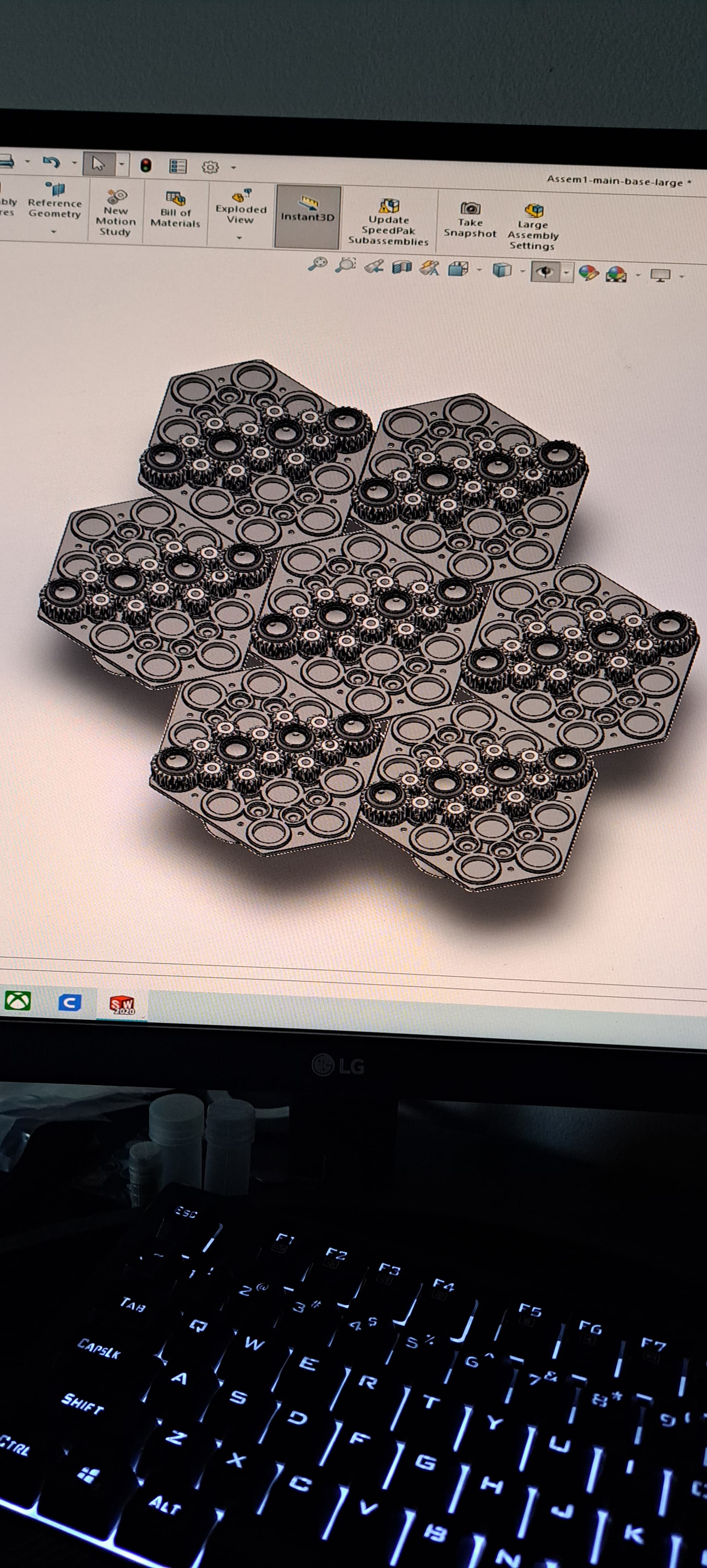
The gears in the pictures. They will be moving at different speeds, so a speed controller is a must and should be able to reverse the motor aswell. what goes on top are graphic imagery tyles if you put in a certain way we get an art piece. So what i am looking for what components should i get to make it happen.
I want to controlle close to 67, chancs 555 24v dc motor. And in the images its show some hexagon tyle with gears, each tyle has 1 motor. Meaning there going to 67 tyles in total each with a motor. And i want to controlle them. Any ideas?
Yes, measure the torque required for the hardest to move gear set that will be the torque required to move the gears.
Are these real gear teeth that have a curved surface so the ROLL together or are they cheap "sliding teeth"gears? Makes a huge difference in required torque. Both will require lubrication.
Ok. I will do that. The gears are made by equation. So they are accurate as they can be from a 3D printer, to just make the first few prototyping before going full ham. (Things are costly) the max voltage on the motors is 24v.
So they will generate lots of sliding friction. Best to lubricate with some type of wax. But you still need to measure the torque required to move your project so you will know if your choice of motor will actually work. How are you attaching the motor to the gears?
For just a few you can probably use the part in Post #3. For the total number you may be wayahead making your own driver board. That part will give you both speed and direction control, At this point I can only guess as we know nothing about the motor requirements such as amps etc. Here is a 5A Ic just to give you an idea. https://www.nxp.com/docs/en/data-sheet/MC33886.pdf My search term was "5 amp H-Bridge IC with MOSFET output",