but the the problem is that i don't know if you could use it to reverse.
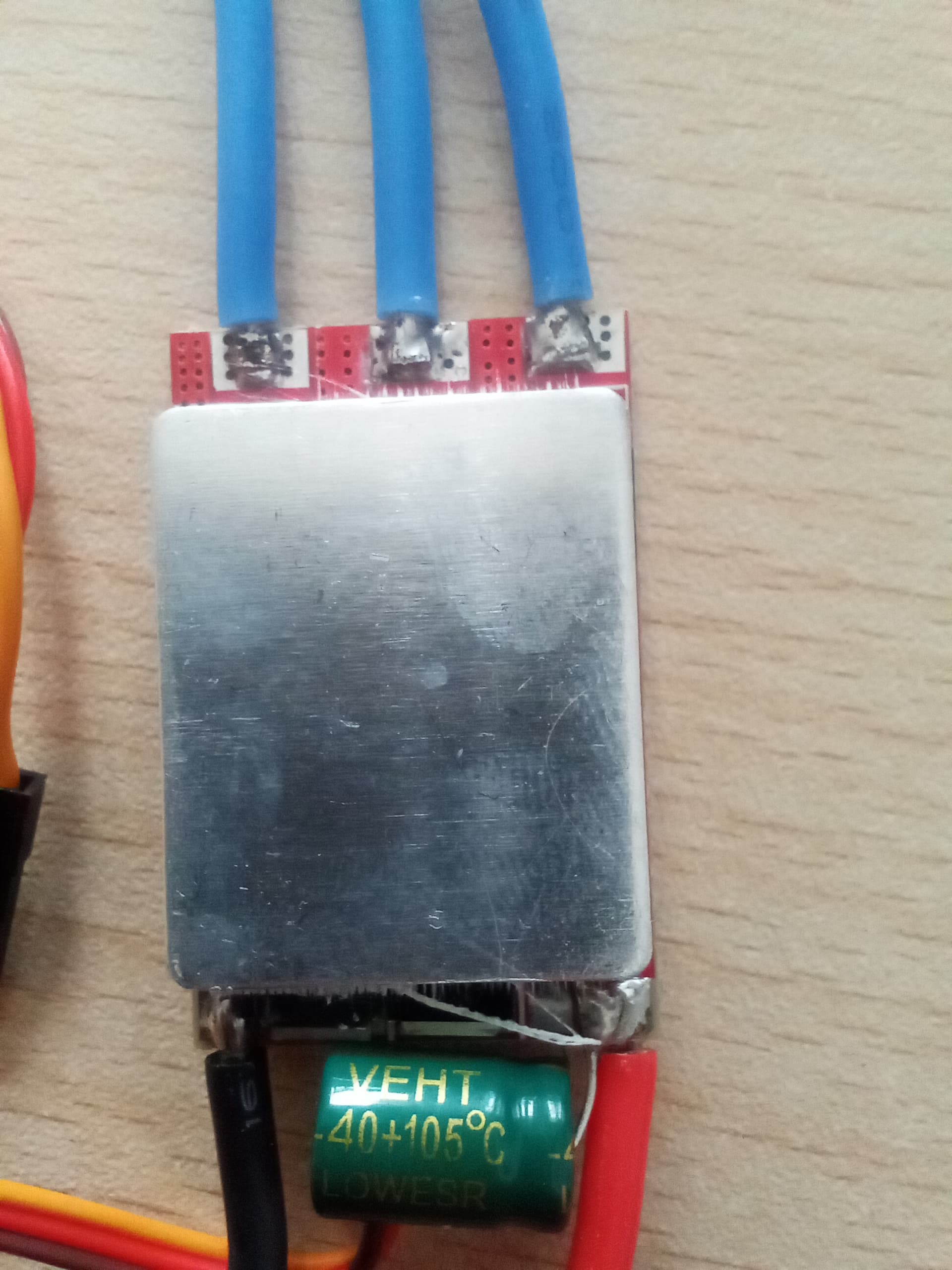
I tried looking for type of chip it uses so i could install a new firmware but it's scratched/ hidden.
It sounds like you know what you are doing. The only idea I have is to try the better known configurators and see if any of them recognize the device and allow setting it differently or uploading new firmware.
After that fails, you could start with the better known stick gestures used for calibration and in some cases allowing parameters to be changed, however slightly.
On a time = money basis, you would probably win by tossing this and buying a new unit from a reputable dealer so you know you have BLHeli 30A 6s ESC, or whatever.
And get back to having the kind of fun you really want to.
thanks for the quick reply.
But in case i don't find a firmware for the ESC or can't buy a new one, is it possible to achieve reverse movement using a 2-Channel relay module?
Maybe something like this :
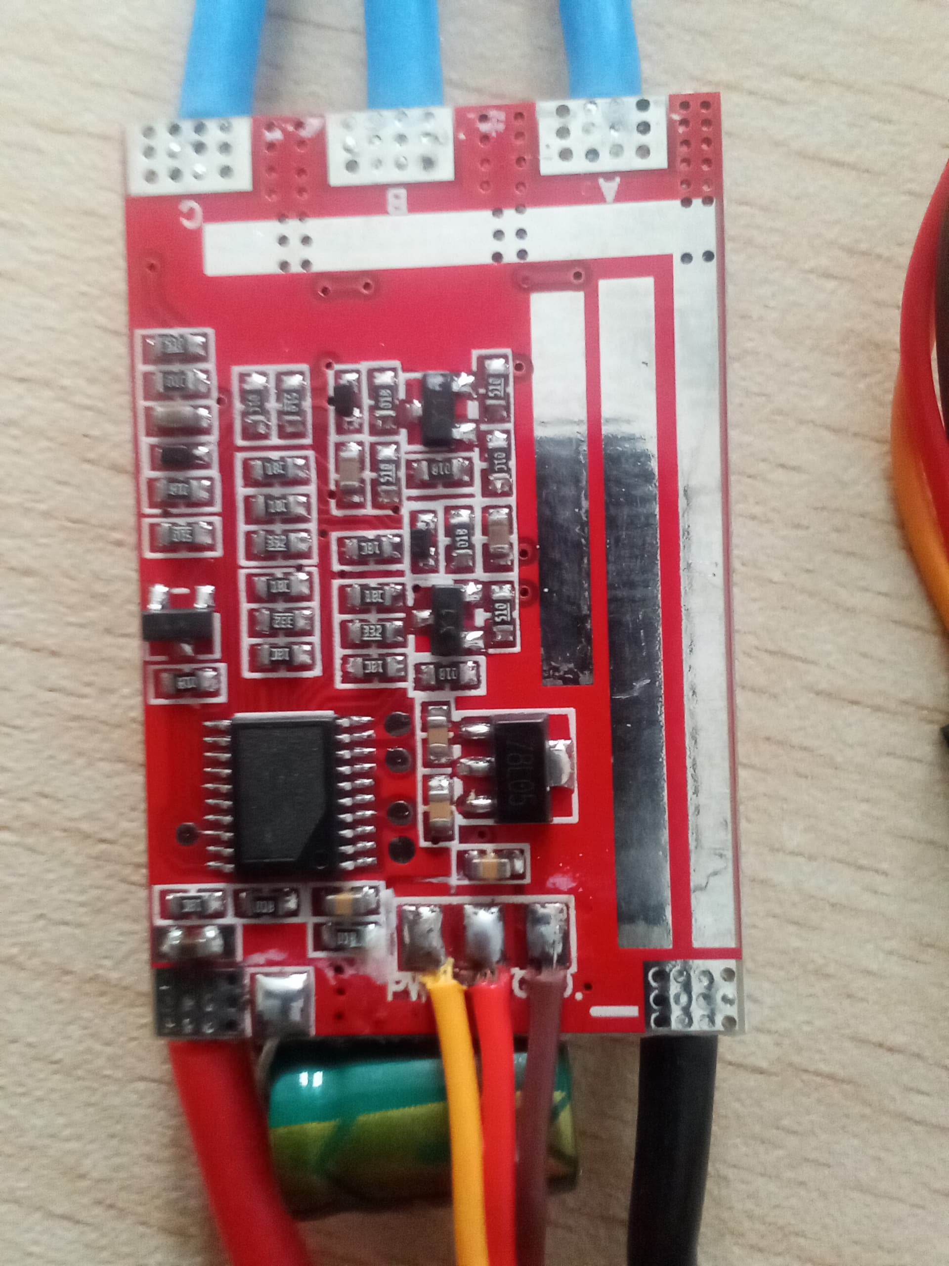
In your picture:
On the left side the pad to pin 18 is ICPCK (clock)
on the right side the pad to pin 9 is VDD, to pin 8 is ICPDA (data), to pin 4 is RST (reset) and the last pad is GND.
(Datasheet Apr. 21, 2022 Page 257 of 278 Rev. 1.10)
IN-CIRCUIT-PROGRAMMING (ICP)
The Flash Memory can be programmed by “In-Circuit-Programming” (ICP). If the product is just under development or the end product needs firmware updating in the hand of an end customer, the hardware programming mode will make repeated programming difficult and inconvenient. ICP method makes it easy and possible without removing the microcontroller from the system. ICP mode also allows customers to manufacture circuit boards with un-programmed devices. Programming can be done after the assembly process allowing the device to be programmed with the most recent firmware or a customized firmware.
There are three signal pins, RST̅̅̅̅̅̅, ICPDA, and ICPCK, involved in ICP function. RST̅̅̅̅̅̅ is used to enter or exit ICP mode. ICPDA is the data input and output pin. ICPCK is the clock input pin, which synchronizes the data shifted in to or out from MCU under programming. User should leave these three pins plus VDD and GND pins on the circuit board to make ICP possible.
There was a recent thread on these fora, forget which one, Project Guidance, Programming or General Electronics certainly.
The overwhelming opinion was that such an arrangement would be a Bad Idea.
OK found it
Read it and make your own conclusion. If the motor has no zero,power going to it, and it is not spinning, it might be OK to do the swap two wires with a relay thing.
I would not depend on those conditions to be true every time. You would be putting the ESC in some risky position.
Good catch. A bit of googling suggests that such an ESC with that microprocessor is running SimonK firmware.
Which may mean it might already be capable, but not yet configured, for forward/reverse control.
Think you will find your robot uses stepper motors not brushless.
In which case, start again.
In any case , esc if aircraft type would be one direction requiring arming.
Land vehicles would have reversible BUT to go into reverse normally requires a " sequence" of throttle movement. Also brake would need most likely to be disabled.
Sry, false hope. I got a hit on the microprocessor part number plus simonk, but the website did not actually mention SimonK.
Later a list of microprocessors that use SimonK did not list that one.
Can you post a link to any technical documentation on the arm/manipulator? I'm curious now for some reason about what kind of motors there are even in that thing.
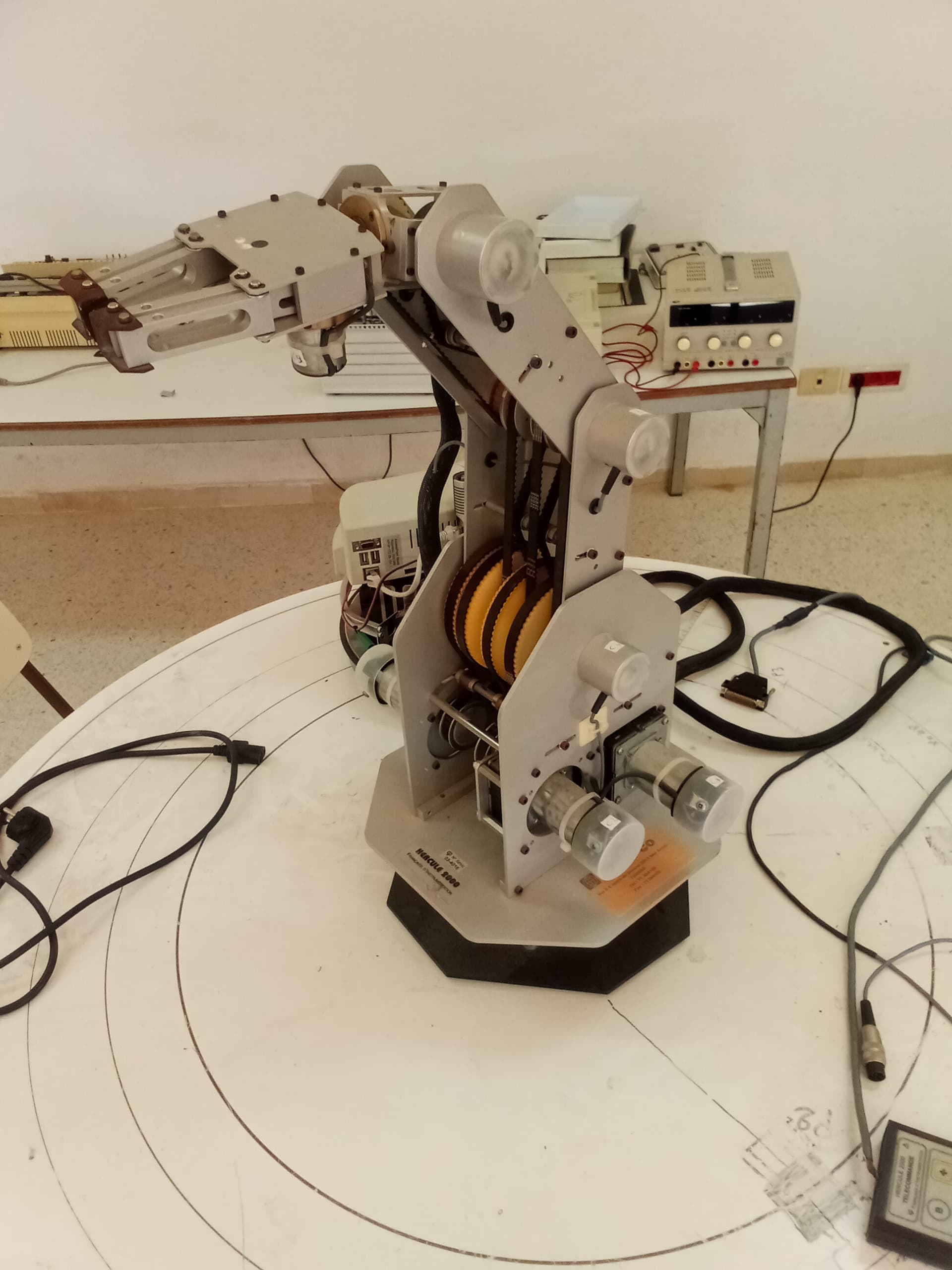
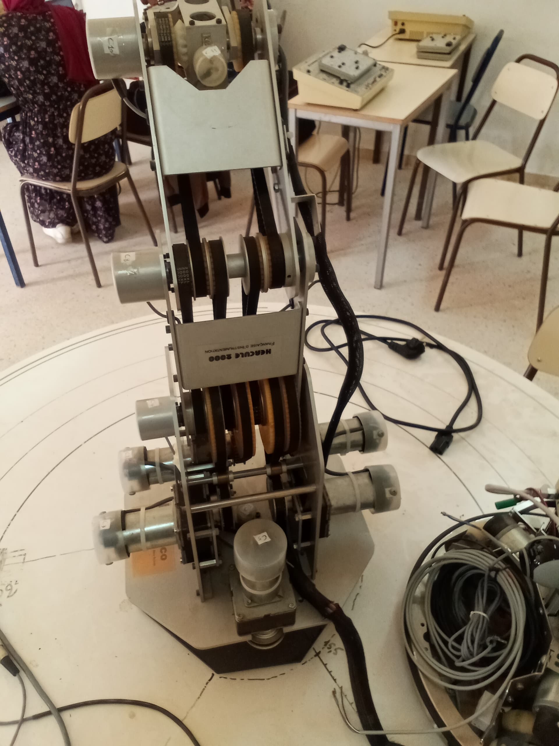
Its part of my end of year project :
Theres an old arm manipulator in our university (Since 2003/2004 i think) that stopped working years ago and apparently the professors told me that the circuit boards in the control box are either missing some parts or the whole board (there was like 5 or 6 circuit boards inside the control box).
So my job is to replace the old control box with a raspberry pi to control the movement of the arm and also add a web interface to control it locally.
When i asked about a technical documentation all they had is some papers that has instructions on how to use it, not the details about parts that i wanted.
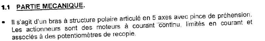
Heres the documentation if you want to read it (it's in french because it's from a french company):
In the documentation it said "The actuators are DC motors" :
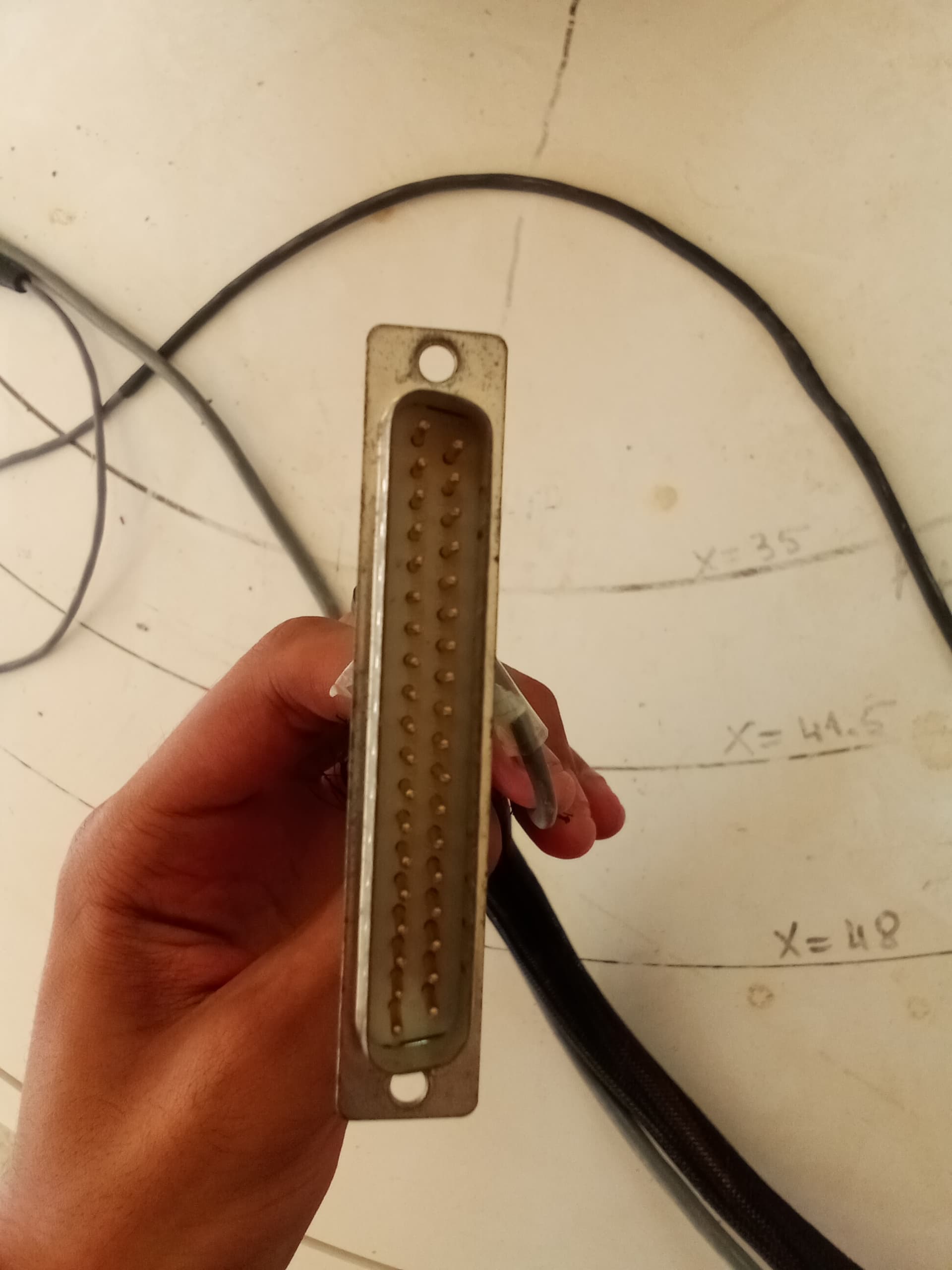
and the cable that connects the robotic arm to the control box has way too many cables for a normal dc motor (11*2 =22 cables) so i assumed it would be a brushless DC motor because they are the the only other DC motor that fits the description.
Also i tried looking for the original company online but apparently they changed type of product they sell or make ?
Tried also contacting them but no response.
Looked online for the same robot but only result i found is from old website with programming language i couldn't understand ( help me if you could recognize what programming language that is ) : http://www.metz.supelec.fr/metz/recherche/ersidp/Software/Nono/Hercule.html
There are many types of dc motor therefore your assumption is incorrect.
My original suspicion was that they are stepper motors. Some have 4 wires, some 5 and others 6.
This probably explains the cable numbers you refer to.
If you look at the cabling coming from each motor it might give a clue, better still any details printed on the motors.
Then again, they might be geared dc motors with encoders run on the back of each. If the encoders are quadrature, then even more cabling to track direction as well as distance.
Biggest hurdle is it's a discontinued item with zero follow up specs or details.
Wouldn't surprise me if they went down the gurgler.
Googled "hercule 2000".....zero, zilch, nothing.
From the pics, I think it's a mix of motors with encoders, plus extra encoders "potentiometers de recopie"=feedback potentiometers(?) on several joints. Maybe the actuator doesn't need an extra encoderpotentiometer, so the 6DOF arm could use 6 motors and 5 encoderspotentiometers = 11 motorish-looking things that combine into 5 servos + one actuator.