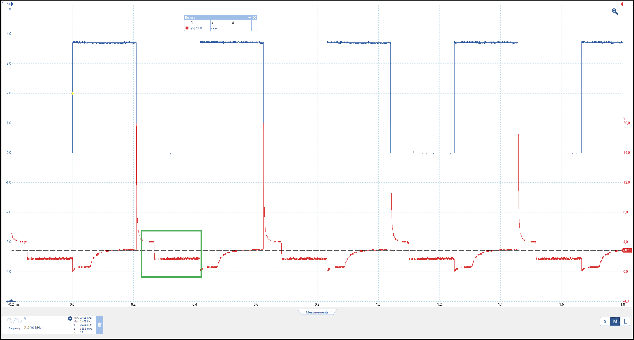
I measure the uC drive signal and the voltage on R8 / 150R. Blue is the drive signal, red is the voltage measured between BJT and 150R. The Collector-Emitter voltage looks good (basically 0V), when the drive signal is at high level.
The interesting part is when the drive signal is at low level (lower picture green bracket). First I thought that the BJT cannot turn off and current still flows, but as I realized that the voltage is the same at both ends of the resistor, current cannot flow.
Could it be the induced voltage of the Buzzer after BJT switch OFF? The relatively big spike seen immediately after switch off suggests that some kind of inductance is there.
Hi, @amazed
You have got the gnd of the Vbatt connected to the gnd of the uC?
Tip, When describing test points that the scope is connected to, put the test points a A, B, C on your schematic, is easier than trying to understand descriptions;
Make all your scope pattern measurement with respect to gnd, that makes comparisons a lot easier to diagnose.