Long time reader, first post. I’m working on a project and I would really appreciate your help.
I want to control 12 auxiliary led lights (off road lights) on my vehicle(12V) using the arduino. The light with the highest power consumption is 355W so around 30A, all the other lights range from 60W to 5W.
I’m using a Nextion HMI as the switch panel that communicates with the arduino Mega 2560 via rx, tx. This side of the project is already working, right now I’m using LEDs on a breadboard to simulate the high power led lights and I’m able to turn on/off the LEDs from the HMI.
To power on the arduino and HMI I plan to use a cigarette lighter or 5v converter.
The problem is I’m lost on how to control these high power led lights with the arduino. I been reading too much on possible ways to control them that I got confused.
I do not want use mechanical relays since it would take too much space and I also want to be able to pulse the lights (strobe mode).
Which leads me to believe that the best option is to use Mosfets, but there’s a lot of options so I’m totally lost as to what to choose.
I have read that maybe a can use logic level mosfets and just connect them to the arduino but I’m not sure if the arduino is going to be able to drive the 12 mosfets needed.
Or I can use power mosfets with a gate driver.
I saw one example were they used a power mosfet and an npn transistor to drive the mosfet but I wasn’t able to understand that.
Since this is going on my vehicle I want to make it as bulletproof as possible.
I would really appreciate any guidance you can give me.
The Mega has plenty of I/O, some 54.
External power supplies are need for those LEDs. Logic level MOSFETs will be fine but get a capable one handling 30 Amp.
Choose MOSFETs with a current rating higher than the maximum current your LED lights will draw. Since your highest power LED light draws 30A, select MOSFETs with a higher current rating to provide a safety margin. You can use IRFZ44N.
I’m not sure if the arduino is going to be able to drive the 12 mosfets needed.
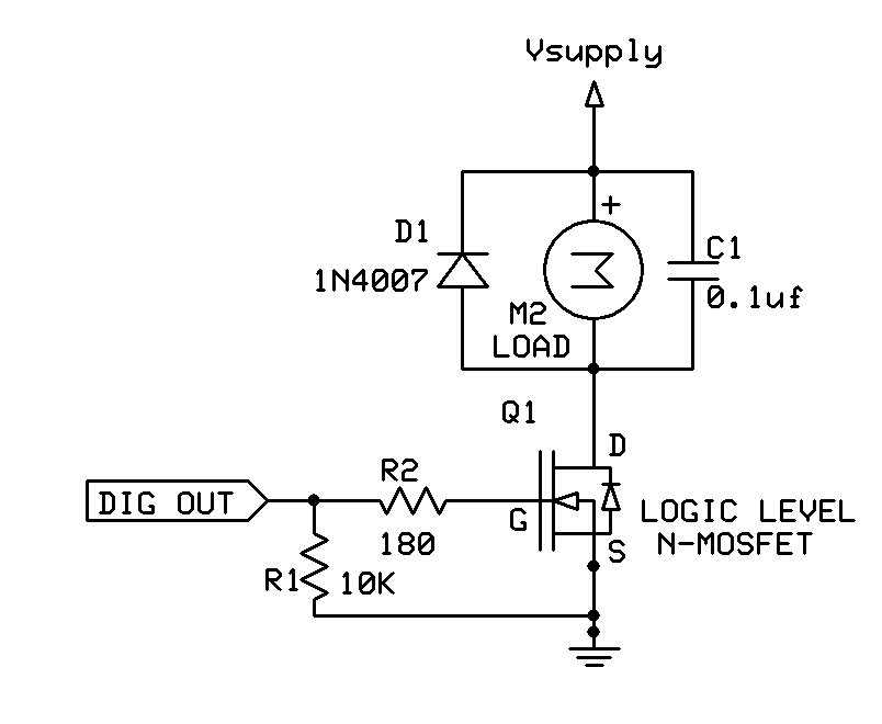
No problem, as long as you use logic level MOSFETs, capable of handling over 40 A. The one linked above is a good choice. Typical configuration (ignore the flyback diode):
You should use 5 V from on the controller in order to have sufficient gate-source voltage to control mosfets. You will need mosfets, that have a specified low Rdson when Vgs is 4,5 V. Not all of them got that.
I would not agree to IRFZ44N, because the max current for Vgs=4,5 V would be about 15 Amps. So the on losses will be two high. I guess this is what @jremington means. He refers to the IRLB8721, and it is specified to have max 16 mohm at Vgs=4.5 V. At 30 Amps it makes 14 W of power loss, so it will need significant cooling.
I would go for a transistor like IRLB3034 or IRLP3034. They have got a max of 2 mohm at Vgs=4.5 V. The cost each is about $3. At 30 Amp the power loss will be about 1,8 W, so it may need to mounted at some small heatsink or metal.
If you want to switch on and off the LEDS at a high frequency, you may need some more powerful driver for the mosfets, because then you need to be aware of switching losses.
Handling this kind of currents are not trivial, and I hope you got the skills for that and use appropriate fuses, so you do not by accident start a fire.
I agree -- these are much better choices. The link I posted was just an example.
Non-logic level MOSFETs are also fine if you use a gate driver IC, which will also decrease the switching time but adds to circuit complexity. The same considerations of lowest possible Rds(on) still apply, for the one 355W light.
The other, lower power lights can easily be driven by the transistor I linked in post #4.
Thank you all for the answers and recommendations.
Handling this kind of currents are not trivial, and I hope you got the skills for that and use appropriate fuses, so you do not by accident start a fire.
This is exactly why I am being very cautions about this project, I want to make sure that I don't have any issues so I'm not rushing to just throw components without knowing their limitations or how they work. I don't mind if the circuit gets complex or expensive.
What would be the best approach to safely handle 30A? is the gate driver the best way?
I was able to look at one device like the one I'm trying to make, I tried to reverse engineer their circuit but it was more difficult than I thought at least for my knowledge. I'm trying to make a diagram of it so that I can show it to you
Another problem I have is for the PCB, I don't have experience designing them so that's another thing I have to learn. unless I can get away with a properly built prototype pcb.
Definitely a problem! There are strict rules for track width and copper thickness on high current PCBs.
Best to have a PCB professionally designed, or construct the circuit on perfboard with extra solder and heavy(*) wires in parallel with the high current traces.
Wear safety glasses or a face shield when testing any high current circuitry, to avoid getting blobs of molten lead and copper splattered into your eyes and face.
A companion told me that he has quit doing high current jobs after a transistor blew up near him - his coat was pierced by shrapnells (he worked in a power grid that time)
You could also bypass that and go with adequately rated SSRs
Either way there's the problem of vibration to deal with. Dupont connectors can be unreliable when single conductors are used, like on a breadboard. Some folks go to multiple position duponts so each position helps hold its neighbor in place. The multi position ones can also be strapped down so they don't come loose. A caveat about dupont connectors - some find them difficult to construct properly.
A 12 V battery got a lot of power and can easily supply 200 Amps to a small wire, that blow up in your face with melted metal. Your car will typically already have a place with some fuses for the different parts of the electrical system in your car, so the cars electrical wires become safe. You need to do the same with your installation. I would not go above 10 amp fuses. If you need the 30 Amps one place, then try to make this the only one. You can get such fuses that are used for cars. They will protect you from the worst accidents and blow before things elsewhere gets dangerous.
I would use some prototyping board with holes and no copper and only solder solid copper leads of right size.
The IRLB3034 will need a charge to the gate of about 160 nC for each shift. Assume you provide a drive current of about 10 mA direct from Arduino, your rice and fall times will be about 16 us. I can make an rough estimate, that the 30 Amp transistor will have a mean power loss of about 52W during this transition. If you switch the transistor by 100 Hz you get 200 transitions each second. It will add a power of 0,17 W in switching losses to the transistor, and it is not that significant. I do not think, that you will need to go higher up in frequency, so a driver should not be required. However, you will need to verify my estimate here.
so I think I was able to trace the circuit on this power control system, that is doing basically what I'm asking on this forum.
If I'm understanding this correctly all the components on the top are for the microprocessor so I don't have to worry about that since ill be using the Arduino.
The 5V on the left side are just for reference that trace goes from the Microprocessor to the gate of the FMMT493 Transistor, I was able to get the resistor values but not the capacitor or the part number for the Mosfet. I can also see that for the 30A circuit they only added another mosfet in parallel.
This looks simple enough and it has been working without issues, but too be honest I don't understand what the circuit is doing or if there's a better way to do this
Did you make this diagram from investigating the PCB of this power control system?
Did you miss the fuse in the diagram?
It is hard for me to read your diagram. I like to see a diagram, that will make clear what parts are on this PCB and what are external parts. Terminals to the PCB should be indicated in diagram.
You will need to cut the wires from the previous processor to each individual control circuit, and connect a wire for control the right place. It may be a bit difficult to do, and to verify that the circuit is correct.
I might be possible for you to remove the "472" input resistor. It could be 4700 ohm. In this way you can disconnect the precious processor. Then add another resistor externally when you connect to the Arduino.
The schematic I tried to do was only for 1 of the circuits being pointed to. i believe that’s what is controlling the main mosfets. All of the circuits next to it are the same with the exception of the last two (30A) those have an extra resistor and 2 mosfet in parallel. The “led” on my schematic is to represent the load (auxiliary lights). I did not included the fuse.
It was hard to follow the traces on the pcb so I used the continuity mode on the multimeter to know where everything was connected to, I have no experience doing this so it might be the wrong way to do it.
The “12v” on the schematic is the positive bus on the PCB board and all the grounds are connected to the negative bus.
The 5v come from a microcontroller that is on top of the PCB.
Thanks for the description. The numbers on the resistors - did you read them on the components. I would guess so. If that is true, then you need to read the third number as the number of zeroes after the two first numbers. So you get 4700 ohm, 47000 ohm, 510 ohm and 1500 ohm.
As I wrote before, you will be able to disconnect the previous controller by removing the 4700 ohm (or 4k7) resistors and mount a wire on the to the pad for the resistor connected to the base of the first transistor. Then you have to get discrete 4k7 ohm resistors for connection to an output from the Arduino, and then you can use this PCB almost directly