Help to identify IC(some kind of logic to analog voltage output switch) [SOLVED]

Hello,

I have an IC which has the markings erased and I would like to find out a similar IC that I may use for a clone circuit. Or at least to find out how this type/class of ICs are called. I realize that the chances of finding the exact model of this IC are slim.

I have attached two pictures with drawings describing the IC and how it is tied to an Arduino NANO in the current circuit.

First picture describes the IC as follows: IC pin 9 is VIN and receives somewhere between 11.5v-12v; IC pin 10 is ground; IC pin 1 receives 5v from the Arduino pin A3 and when this happens it sends VIN to IC pin 18; IC pin 3 receives 5v from the Arduino pin A5 and when this happens it sends VIN to IC pin 16;

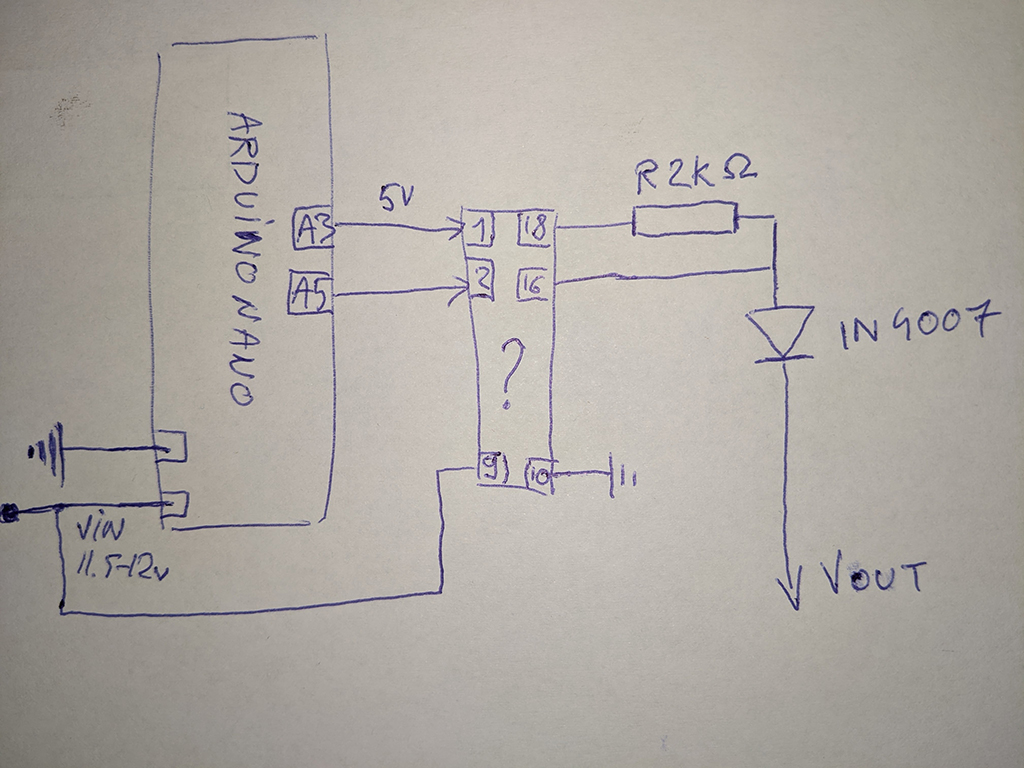
Second picture describes the circuit, IC + Arduino NANO, and what it currently does:
Arduino GND and IC 10 are connected to ground; Arduino VIN and IC 9 are connected to 11.5-12v.
After voltage is supplied, Arduino waits 1.2s then outputs 5v for 1.2s across A3 (connected to IC pin 1), and in turn the IC outputs VIN on IC pin 18 for the 1.2s duration.
After that Arduino waits another 1.2 seconds and then outputs 5v for 1.2s across A5 (connected to IC pin 3), and in turn the IC outputs VIN on IC pin 16 for the 1.2s duration.

IC pin 18 is connected through a 2K resistor to IC pin 16 and both of them are followed by a 1N4007 diode (but IC pin 16 is not in series with the resistor), then comes the final output which is hooked up to a trigger mechanism in another circuit.

When no voltage is applied to IC pins 1 and 3, then 0.01V may be measured on IC pins 18 and 16.
When 5v is applied to IC pin 1 then VIN with a drop of 0.02V may be observed on IC pin 18, the same happens with the pair IC pin 3 and IC pin 16.

I know that I should not connect an Arduino to 12v but I have the option to add a LM7805 and power the Arduino through the 5v pin later on.

Does anybody have any info on an IC which may replace the one described?

Thanks a lot!

LE: in the second picture I mistakenly numbered the IC pin 2, instead of 3.
LE: packaging is PDIP-18
LE: Where its written 'Vout' in the circuit, that's where I get voltage output when the pins are triggered on the IC. And that 'Vout' is connected to an external circuit (that is outside of my control). Sometimes that external circuit sends voltage back to my circuit, but that's not something I have to worry about, that is why that diode is placed there. Maybe instead of 'Vout' I should have written 'External Circuit'.

SOLVED: IC in question is MIC2981/82YN.

ULN2008?

Looks like it might be a power driver similar to a ULN2008. The clue is pin 9 going to + 12 VDC. This connects the cathodes of the internal flyback diodes for suppression. Hope this helps and note that there were several variations of this part - different numbers of drivers on a 16 or 18 pin device !!

Thank you very much @groundFungus and @62Tom !

What I could find locally is only a ULN2003APG (in a motor driver PCB at $1.5 :slight_smile: ) and this is similar to ULN2008, 5v TTL and up to 50v output.

I will report back next week after I try it out.

Thanks again, all the best!

I think ULNxxx are open collector only. That can pull LOW but not push HIGH.

@Smajdalf, my analog electronic skills resemble a rat's movement in a new maze, so I'm pretty much guessing stuff.

Do you have an alternate IC suggestion? It wouldn't hurt to get another extra type so I don't have to wait again in case something doesn't work with the ULNxxx series.

I think you can add a PNP BJT (or a P-MOSFET) to the outputs of the ULNxxx to get the desired behaviour.
You can also drive the transistors with a discrete NPN (N-MOSFET) transistors instead of the ULN.
In both cases you can probably remove the diode.
You can try CD5404 CMOS level shifter but I guess it won't be able to provide enough current.
You can also use some H-bridge chip. Or an op amp/comparator with rail to rail push-pull output.

UDN2981/2?

@Smajdalf, thank you for your reply! I'm trying find an IC to make the circuit copy work the same way as this one without added components. The CD5404 will not probably work, but I may try adding a PMOS to the ULNxxx if it doesn't work directly.

@PaulRB thank you! I'll try getting that too, if I can find it around here.

I'll keep my tries between ULN2003 and UDN2981, it seems like one of them has to do the job.

That looks more like a high side driver to me, say UDN2981A, with those voltage measurements and that diode.

Are you using only 2 outputs of that chip ?
In that case, there may be other ways of achieving the same thing.

The UDN has a Darlington pair as output. Is it ale to pull 0.02 V to the positive rail as OP have measured? Maybe with no load. Is it enough?

Smajdalf:
The UDN has a Darlington pair as output. Is it ale to pull 0.02 V to the positive rail as OP have measured? Maybe with no load. Is it enough?

I would guess the voltage measurements are approximate.
That circuit does, though, look like it is expecting a high side driver, otherwise, for example, Vout at the cathode of a 1N4007 is not going to be very useful. Or maybe I am missing something.

@6v6gt Where its written 'Vout' in the circuit, that's where I get the voltage when the pins are trigger on the IC. And that 'Vout' is connected to the trigger circuit (that is outside of my control). Sometimes that trigger circuit sends voltage back to my circuit, but that's not something I have to worry about. Maybe instead of Vout I should have written 'External Circuit'.

This is one of the first times I am trying to describe a circuit.

OK. But what is this system? It appears that setting pin A3 on the Nano to high delivers approx 6mA at a bit less than 12 volts to your external circuit. Maybe this is a short "warm up" phase. Setting pin A5 high delivers substantially more current.

I guess you've understood that the band marking on the 1N4007 indicates its cathode so, in this case, the end with the band must be "nearest" to the "external circuit".

The "external circuit" must share a common ground with the driver chip, or is there some other connection which has not been shown ? Anyway, can you also measure the voltage between the "output" of that diode and ground (of the external circuit during the 3 phases you have mentioned. If that is difficult (1.5 seconds may not give a stable reading, depending on the test instrument), just the voltage at the end.

Edit

If it is a UDN2981, you'll have trouble finding one. Mouser has this alternative: MIC2981

@6v6gt thank you for the additional information!

The "external circuit" unlocks a door when receiving two signals between 11.5 to 12v timed as in the OP. I have no other control over the "external circuit" nor do I know how it looks.

My circuit replaces an apartment intercom system and automatically opens the door when the intercom rings (powers up). I have a already functioning circuit wired as described in the OP which does exactly this, but I am missing the IC to duplicate it.
My goal is first to find a working IC and duplicate the circuit, so that I may auto-unlock the door, and then move over to an ESP8266 (instead of the NANO) to control the door from my phone.

The band marking cathode on 1N4007 is "nearest" to the "external circuit". The "external circuit" sends back some signals, but that is none of my concern because I only have to send the two 11.5-12v impulses to the "external circuit" to unlock the door.

The "external circuit" does share a common ground with the NANO and the driver IC for everything to work.

Thank you for the alternative MIC2981, I was having trouble finding the UDN series.

OK. In that case the first pulse is probably a signal which, say puts a buzzer tone on the speech channel, or something similar. The second pulse operates the lock mechanism (which probably draws a substantial current).

The chances are then good that the chip is a UDN2981. Also, redesigning the circuit to use readily available components would then be easy. In those circumstances, I would probably use two P channel mosfets and two opto couplers and the mosfets would not even have to be logic level. But there are also many other alternatives.

I finally got some parts in today (UPS is playing hide-and-seek), and just replaced the mysterious IC with the MIC2981/82YN, powered on the Nano with 12v on VIN and everything works the same as before, this is great!

Big thank you to @6v6gt and everybody that helped!

Now, out of curiosity I tried to draw a high side switch to switch 12v with 5v using a NPN and a PNP, on CircuitLab, it seems to do the job on the simulator and it looks like this High-Side Switch NPN->PNP - CircuitLab
*grounds are tied/common; the MCU is simulated with a Voltage Function Generator that sends a 1s square 5v every odd second; the Q1 transistor output is 12v whenever the VFG output is 5v.

Would this be able to replace just one of the switches on the MIC2981/82YN ? I would like to learn of more ways to do the same thing as these will surely be useful later on.

I'm pleased that had a happy end.

In your simulation of the high side switch, can you measure the current going into the bases of those 2 transistors ? Usual is to have a current limiting resistor. Otherwise it looks OK but is drawn rather unconventionally.

For the door lock, you probably need a current higher than a 2N3906 can tolerate. I'd probably use a circuit like this, which also gives some isolation to your Arduino development:

That design was used, incidentally, in this project. Controlling 4W neon lamp working with 12V external power - General Electronics - Arduino Forum

" CD5404 CMOS level shifter"
Are you sure you don't mean CD4051BE ?

From datasheet

The ULN2803Ais comprised of high voltage,high current NPN Darlington transistor pairs.All units feature a common emitter and open collector outputs.

@OP,
I think you can edit your Original Post to read [SOLVED]