Hello,
I've been trying to make the MSGEQ7 circuit work with arduino for the past month or so, unsuccesfully. I've gone through many forum posts, tutorials, etc., but got nowhere.
I've tried a soldered prototype board aswell as several breadboards started from fresh.
The IC keeps outputting the same values on all channels no matter what sound i connect to it. Same thing happens when no audio is playing, or when the audio jack is not even connected to the IC.
Please advise on what I'm doing wrong, I'm completely drained of ideas
testing arduino board is an Arduino Nano clone with CH340
Wiring is the same(as far as i know) as the MSGEQ7 datasheet recomendation
5 different MSGEQ7 integrated chips tested, MSGEQ7 1902, 3x from one supplier, 2x from another (both china based), completely same output, no variations between tests
Tested with 3v3 output, 5v output and external 5V PSU
GNDs all connected
Analog input on Arduino works, as it reacts to pure headphone signal - 0 when no sound, values when sound present
Tested several code examples found on the internet
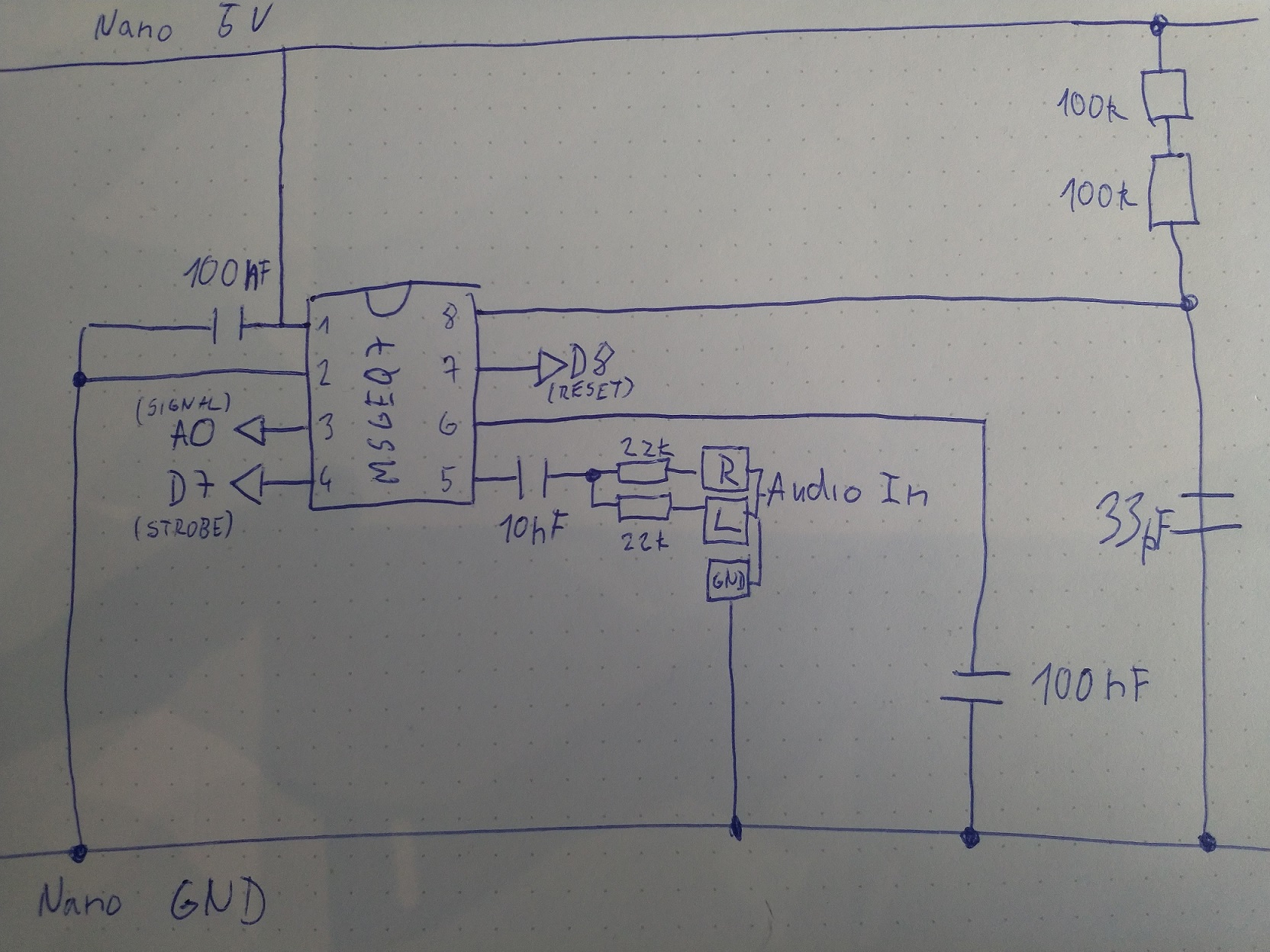
Diagram of my wiring and exact components is in the attachment
standard ceramic capacitors (33,103,104) are used.
This code is currently used for testing:
int analogPin = 0; // read from multiplexer using analog input 0
int strobePin = 7; // strobe is attached to digital pin 2
int resetPin = 8; // reset is attached to digital pin 3
int spectrumValue[7]; // to hold a2d values
If you have an oscilloscope or multimeter, here's what I suggest* -
Change all of the delays to something like 1 minute.
Then confirm that the Reset & Strobe lines are activated in the sequence shown in the timing diagram on the datasheet.
You can also monitor the MGEQ7's Output with loud & quiet sounds, but that shouldn't be necessary since you know the Arduino's analog input is working.
The times shown on the timing diagram are minimums. And, you can actually stop or make a super-long delay after the first (63Hz) band is activated so you'll just be reading the bass.
If you don't have any "tools" wire-up a an LED & resistor as high/low tester or put one LED on the Strobe and one on reset so you can see the states. You may also be able to monitor the Output but you may not get enough voltage to turn-on the LED.
Two LEDs permanently connected might actually be the best way to do it but it's a little more work than touching a probe.
Wiring is the same(as far as i know) as the MSGEQ7 datasheet recomendation
Can you post a photograph of your wiring as it might not match up with the actual diagram you are trying to follow. If this is so it will not be the first time a mistake has been made like this.
int strobePin = 7; // strobe is attached to digital pin 2
int resetPin = 8; // reset is attached to digital pin 3
This doesn't match up with the schematic you posted. Or indeed the comments don't match with what the code actually does.
Unfortunately don't have an oscilloscope, but the idea with LEDs and slowing the program down is good - will try it when I have a moment.
You're right, the comments don't match - i only edited the code, and forgot to edit the comments. Here's the photo (only one channel on this test, both channels were used in other tests):
I have also been having all sorts of problems with these chips. I'd assumed I'd blown some so bought several more. They simply didn't work as I expected, returning near constant high voltages. I hooked up an oscilloscope and nothing made sense. Eventually I bought some ones from SparkFun and they worked in the same circuit.
The pattern I have observed is:
SparkFun chips (numbered 1908) work
Ones ordered from AliExpress and EBay (presumably also from China) and numbered 1902 don't work (I've tried at least 12 in the same circuit which works for the SparkFun ones).
Ones ordered from AliExpress and EBay (presumably also from China) and numbered 1902 don't work (I've tried at least 12 in the same circuit which works for the SparkFun ones).
Thanks for all the replies. The knowledge that more people have bad experience with 1902 chips is exactly what I needed. I ordered 2 MSGEQ7 directly from sparkfun, we'll see
NeutralEagle:
Thanks for all the replies. The knowledge that more people have bad experience with 1902 chips is exactly what I needed. I ordered 2 MSGEQ7 directly from sparkfun, we'll see
What is the result ? I have similar mistake. My MSGEQ7 is 0252
I have a MSGEQ7 from sparkfun. But using this code it only prints 0's i nearly have the same setup,(only missing the resistor at audio in and the condensator of 33pF) but it looks like the 5 pin from the chip is not working, is there anyway to test this?
Right! The oscillator makes the 7 frequency-filters work so you need the correct resistor & capacitor to get the correct clock and the correct filter frequencies. (This is a special kind of switched filter. Most analog filters don't need a clock/oscillator.)
only missing the resistor at audio in
That's probably OK. The schematics I've seen show two resistors for mixing the left & right channels. If you are only using one channel you don't need the resistors. But, you should not short left & right together.