Hello all,
I am a cosplayer using Arduino for the first time, rigging up LED strips to make a "flaming" sword. I have the LED strips soldered and wired in parallel (so both sides of the blade light up) and everything tentatively works on a breadboard. I am trying to build the circuit to be as compact as possible to fit inside a hollow sword grip I can design and 3D print later. I have a few more components I need to add, and that's where I could use some help:
I plan on using a 9V battery to power the sword, with an on/off switch built into the grip. I have capacitors and resistors, but where do I add them in the circuit, and what values of each should I use?
Additional info: Each LED strip (WS2812B) has 43 individual LEDs, so 86 in total, wired in parallel. The code is on an Arduino Nano.
I have capacitors and resistors, but where do I add them in the circuit, and what values of each should I use?
I don't have a schematic of your circuit so I don't know how I am supposed to answer that.
Common sense says a circuit should have some filter caps . In your case, with a 0.1A load, probably 470uF.
I can't comment on your leds because you didn't post a link to the vendor where you bought them so
I have no information on them except the type.
Post a schematic and a vendor link.(and/or datasheet)
If you can't find a link that gives the load current per light string then you will have to measure it with a
DMM.
There are many different products that use the ws2812 so what you have told is essentially nothing.
dl324:
You'll be lucky to get 2 hours with a 100mA load.
That's not a big deal, it just has to light up and look cool for the 30 seconds I'm on stage during the costume contest, while posing for pictures, and pre-judging. I can swap out batteries to keep them fresh.
I measured 800 mA at peak brightness, but the flame code flickers between 200 and 800 mA and not all the LEDs are always on as the "flame" flickers up the length of the strip, so I figure that should extend the life a little more.
The leds are PWM controlled.
The brightness (and hence current draw) are a function of the PWM pulse width.
If you are already using the code you should already know this.
Look for a parameter called Brightness
FastLED.setBrightness(brightness);
I measured 800 mA at peak brightness, but the flame code flickers between 200 and 800 mA and not all the LEDs are always on as the "flame" flickers up the length of the strip,
Because the leds are flickering, the load current maximum is probably 800mA.
So your operating at approx 20% average duty cycle , which puts your 9V battery life at about 36 minutes.
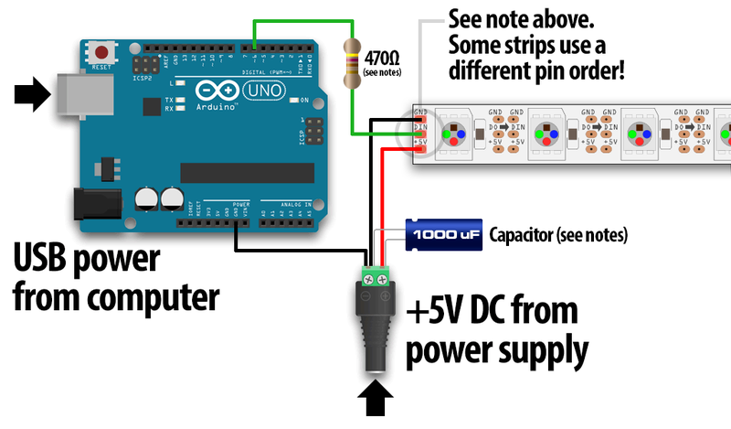
Here's a diagram of the schematic. It works via breadboard, I just have yet to connect the parts directly together. FYI, I am a biologist in my day job and completely self-taught on everything from the coding to the circuitry, so I really appreciate everyone's patience.
I'm trying to learn more--can you tell me why it would destroy the Arduino with the current setup?
I tested it before on a phone charger bank before and the problem was it would work at first but then shut off automatically within a minute, and I'd have to disconnect and reattach the USB cord to turn it on again, which isn't easily done when in full costume. Is there a different model that will continue to deliver power when devices other than phones are attached?
The link you posted was for individual leds , sold from a reel, not a strip.
If you MADE the strip it was your duty to LOOK at that data sheet (that YOU posted) and ask about the caps from +5V to GND at every led. The caps must be wired DIRECTLY to the power (5V) and GND pins of EACH AND EVERY ONE OF THE EIGHTY- SIX LEDS.
If you haven't done that, you need to do that NOW.