How to connect ESP32 S3 WROOM N16R8 CAM OV5640 to TFT ILI9488 or ILI9341, Because it only has 1 VSPI pin

1 Like
Not sure what your question is. Do you have a wiring diagram? I have one of those displays and it works great now but it was a challenge to get it working.

Ok, so what is the question?
In the ESP32 Wroom 32 example, the MISO, MOSI, CS, and CLK pins are connected to VSPI_MISO, VSPI_MOSI, VSPI_SS, and VSPI_SCK. On the ESP32 S3 Wroom N16R8, there is only one VSPI pin. What is the solution?
I still don't understand what your problem is. I see 4 VSPI pins.
The board pictured connected to the LCD is NOT the same as the picture of a board.
You need to be specific. Have you wired your project exactly as you drew the diagram?
Show us a photo so we can evaluate the soldering job.
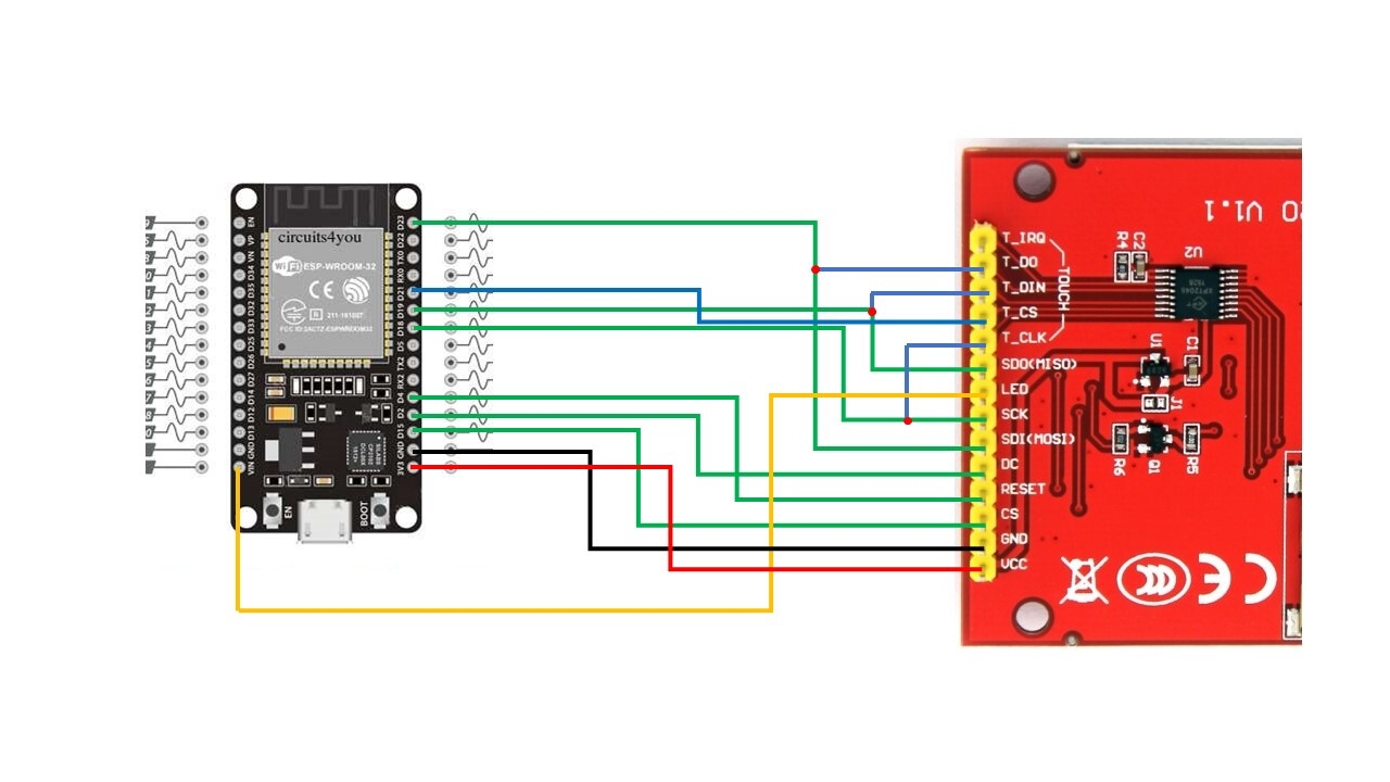
I have a wiring diagram for the ESP32 WROOM (classic) which uses 4 VSPI pins: VSPI_MOSI, VSPI_MISO, VSPI_SCLK, VSPI_CS for the TFT (ILI9341/ILI9488).
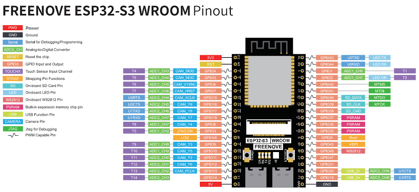
However, the ESP32-S3 WROOM N16R8 (with the OV5640 camera module) I'm using on this board only has one pin marked VSPI on the silkscreen, so I'm confused about which GPIOs to assign to the TFT MOSI/MISO/SCLK/CS.
Please help:
On the same ESP32-S3 WROOM N16R8 board as mine, which GPIOs should I assign to the VSPI_MOSI, VSPI_MISO, VSPI_SCLK, and VSPI_CS pins? (Please specify the GPIOs, e.g., GPIO23, GPIO18, etc.)
Are there any pins that should be avoided due to the OV5640/PSRAM/USB used on this board? If so, please specify the conflicting pins.
Sorry for my bad English🙏
I would have to find the datasheet and pinout diagram for the board you are using. I think you are using the ESP-Eye board. Most pins are reserved, but again, find the datasheet to be sure. You can do that as easily as I; I don't have it memorized.
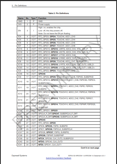
Yoju need the dev board datasheet, that is just the SOC.
With the ESP32 you can assign the SPI pins to most all of the GPIOs, no need to stick to whats labelled on the pinout diagram.
Define the pins in the sketch start like this (or use other GPIOs) ;
#define MOSIpin 45
#define SCKpin 42
#define MISOpin 41
Then start up SPI like so;
SPI.begin(SCKpin, MISOpin, MOSIpin);
I moved your topic to a more appropriate forum category @adibrino.
The Nano Family > Nano ESP32 category you chose is only used for discussions directly related to the Arduino Nano ESP32 board.
In the future, when creating a topic please take the time to pick the forum category that best suits the subject of your question. There is an "About the _____ category" topic at the top of each category that explains its purpose.
Thanks in advance for your cooperation.
Okay, I will try.
Hello, can you tell me how you connected the ESP32S3 N16R8 to this display. What pins are where and what user settings?
No idea what you mean by 'user settings'.
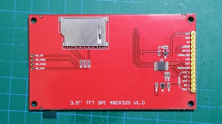
The problem is that display has several variations so mine might not be like yours.
I will give you mine but be aware it will either work, not work, or worst case go up in smoke.
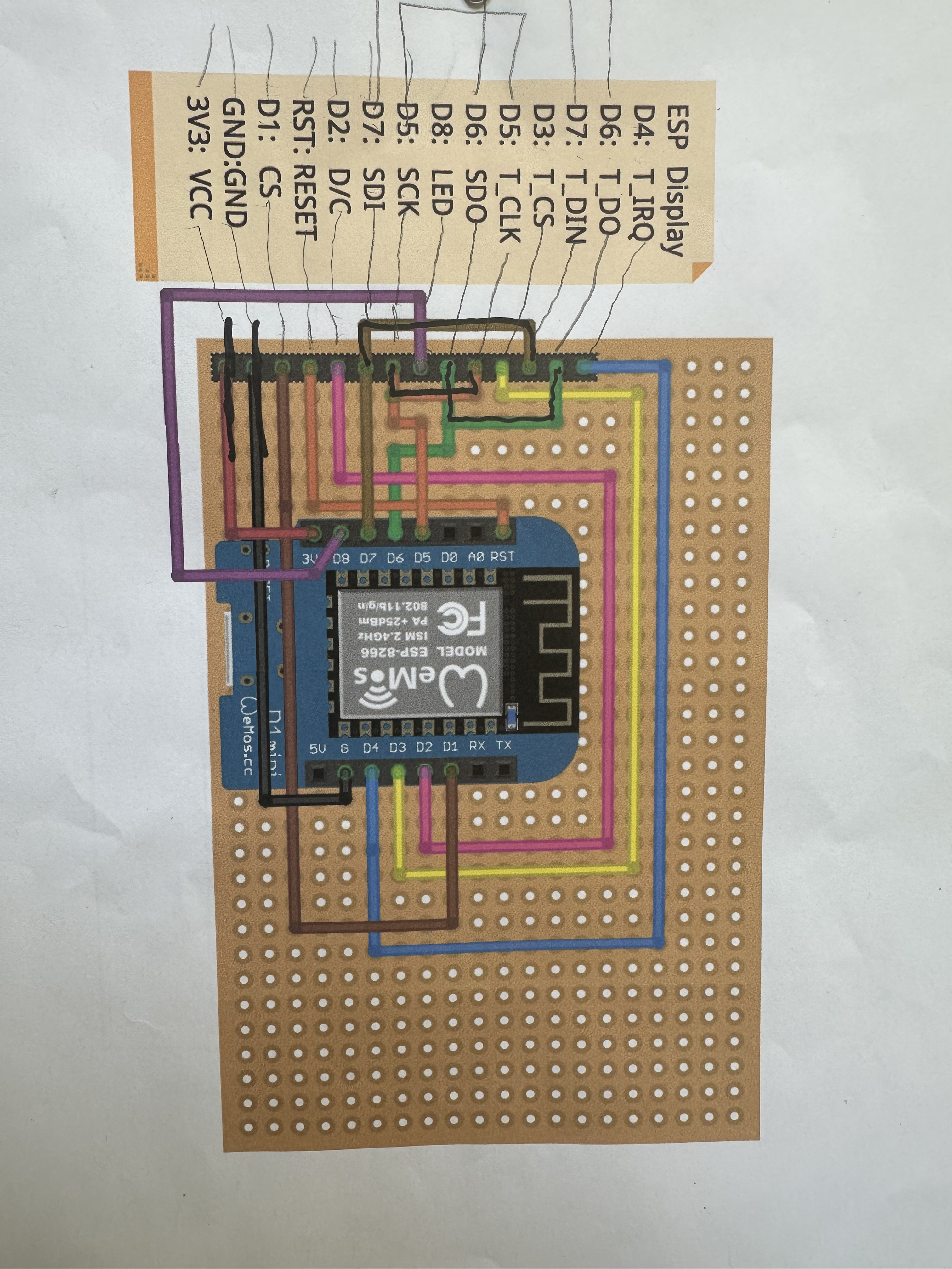
Keep in mind, the processor pins are specific to the sketch I am using. Your project should have all those instructions. If it doesn't, then it's a guessing game.
This topic was automatically closed 180 days after the last reply. New replies are no longer allowed.