How to determine (or improve) BLDC motor at lower speeds when using Back-EMF for timing the 6 step commutation?

Hi!

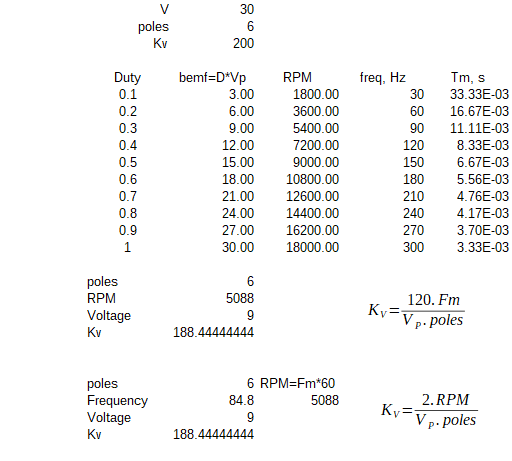
I have a small high speed sensorless BLDC motor (It has 6 pole pairs and 5 ohm internal winding resistance - it's a small high speed driller) that with it's original driver used to run from 2K RPM to 40K RPM, with good torque even at the lower speed setting (2k RPM). It used to draw no more than 3A when in highest torque, and it needs 30V-33V DC to run.

I've being trying for some time to re-create the driver within the same specs with help of ready-available chinese BLDC Sensorless controllers, but, as these drivers are not specific for this motor, there's always some things that don't work as expected, or some trade-offs.

Some of these controllers have a RPM pin output, so I managed to do a Speed closed loop PID, to keep speed constant under load.

So It's being easy to drive the motor with any of the drivers I tested to max speed, but I'm not being able to get to the lowest speed I know it works with any of them.

I even tried some cheap Drone ESCS, but few can withstand 30V or more, and the ones that do are designed for a lot of AMPS (and are really expensive), and I need only 3-5Amps most. And they have all that whistles and startup beeps and routines that for me aren't needed.

I've looked into Benjamin Vedder's VESC specs also, but it seems that the VESC algorithm top speed limit is lower than 40K RPM max speed I need.

Usually, thoses cheap ready-made all-around sensorless chinese controllers sets the min speed possible at 10% PWM at the potentiometer control, or at the pwm input pin, which in my case would be 4-5K RPM.

Some set the min speed to even more, 20% PWM (Like 8-10K RPM). And also their open loop start up sequence are not designed for initial high speed with higher torque . Usually are made to fans, blowers and skateboards, and you can't change their parameters, as their code are written in their MCU and not "programmable" or updatable. I've tested quite a few.

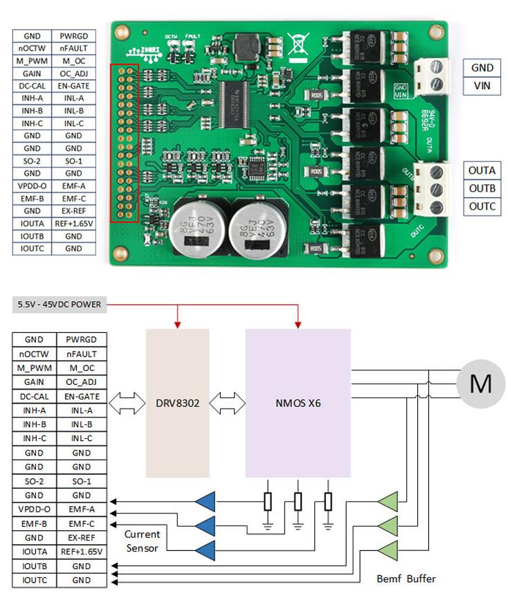
So finally I bought a development board below, based on the DRV8302 chipset that has filtered and buffered Back-EMF outputs (and these outputs are brought to a lower voltage by voltage dividers in each phase), and has current sensors for all three phases.

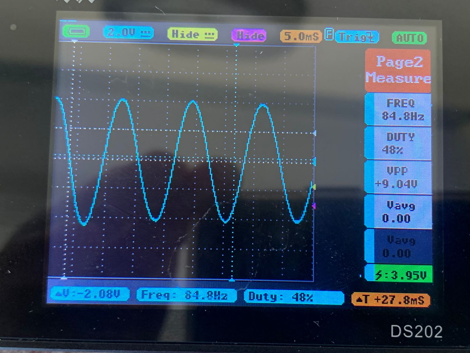
Using an Arduino PRO Mini and with the 6 step PWM driving Sensorless code made by Simple-Circuit, I managed to adapt the code to this DRV8302 board, and make it work really well in this development board, with almost no noise, to more than 40K at the highest speeds! In fact to 47K RPM max, at 33V. Schematics of the original setup below:

In fact, in terms of being silent and current draw it performs better than the all-around-controllers I tested, with little current draw, vibration-free.

The original code by Simple-Circuit is this one: I uses an interrupt to detect the zero-crossing of the non energized-phase to time the 6 step switching frequency. it runs at 31khz frequency PWM.


/* Sensorless brushless DC motor control with Arduino UNO and IR2101 (Arduino DIY ESC).
 * BLDC motor speed is controlled with a potentiometer connected to A0.
 * This is a free software with NO WARRANTY.
 * https://simple-circuit.com/
 */
 
#define PWM_MAX_DUTY      255
#define PWM_MIN_DUTY      50
#define PWM_START_DUTY    100
 
byte bldc_step = 0, motor_speed, pin_state;
 
void setup()
{
  DDRD  |= 0xE0;  // configure pins 5, 6 and 7 as outputs
  PORTD  = 0x00;
  DDRB  |= 0x0E;  // configure pins 9, 10 and 11 as outputs
  PORTB  = 0x31;
  // Timer1 module setting: set clock source to clkI/O / 1 (no prescaling)
  TCCR1A = 0;
  TCCR1B = 0x01;
  // Timer2 module setting: set clock source to clkI/O / 1 (no prescaling)
  TCCR2A = 0;
  TCCR2B = 0x01;
  // ADC module configuration
  ADMUX  = 0x60;   // configure ADC module and select channel 0
  ADCSRA = 0x84;   // enable ADC module with 16 division factor (ADC clock = 1MHz)
 
  PCICR  = EIMSK = 0;  // disable all external interrupts
 
  pinMode(2, INPUT_PULLUP);
  pinMode(3, INPUT_PULLUP);
  pinMode(4, INPUT_PULLUP);
}
 
// pin change interrupt 2 (PCINT2) ISR
ISR (PCINT2_vect)
{
  if( (PIND & PCMSK2) != pin_state )
    return;
  // BEMF debounce
  for(byte i = 0; i < 20; i++)
  {
    if(bldc_step & 1){
      if(PIND & PCMSK2)     i -= 1;
    }
    else {
      if(!(PIND & PCMSK2))  i -= 1;
    }
  }
 
  bldc_move();
  bldc_step++;
  bldc_step %= 6;
}
 
// BLDC motor commutation function
void bldc_move()
{
  switch(bldc_step)
  {
    case 0:
      AH_BL();
      BEMF_C_FALLING();
      break;
    case 1:
      AH_CL();
      BEMF_B_RISING();
      break;
    case 2:
      BH_CL();
      BEMF_A_FALLING();
      break;
    case 3:
      BH_AL();
      BEMF_C_RISING();
      break;
    case 4:
      CH_AL();
      BEMF_B_FALLING();
      break;
    case 5:
      CH_BL();
      BEMF_A_RISING();
  }
}
 
void loop()
{
  SET_PWM_DUTY(PWM_START_DUTY);  // setup starting PWM with duty cycle = PWM_START_DUTY
  int i = 5000;
 
  // motor start
  while(i > 100)
  {
    delayMicroseconds(i);
    bldc_move();
    bldc_step++;
    bldc_step %= 6;
    i = i - 20;
  }
 
  motor_speed = PWM_START_DUTY;
  
  PCICR  = 4;  // enable pin change interrupt for pins PCINT23..16 (Arduino 0 to 7)
  
  while(1)
  {
    ADCSRA |= 1 << ADSC;    // start conversion
    while(ADCSRA & 0x40);   // wait for conversion complete
    motor_speed = ADCH;     // read ADC data (8 bits only)
    if(motor_speed < PWM_MIN_DUTY)
      motor_speed = PWM_MIN_DUTY;
    SET_PWM_DUTY(motor_speed);
  }
}
 
void BEMF_A_RISING()
{
  PCMSK2 = 0x04;    // enable Arduino pin 2 (PCINT18) interrupt, others are disabled
  pin_state = 0x04;
}
void BEMF_A_FALLING()
{
  PCMSK2 = 0x04;    // enable Arduino pin 2 (PCINT18) interrupt, others are disabled
  pin_state = 0;
}
void BEMF_B_RISING()
{
  PCMSK2 = 0x08;    // enable Arduino pin 3 (PCINT19) interrupt, others are disabled
  pin_state = 0x08;
}
void BEMF_B_FALLING()
{
  PCMSK2 = 0x08;    // enable Arduino pin 3 (PCINT19) interrupt, others are disabled
  pin_state = 0;
}
void BEMF_C_RISING()
{
  PCMSK2 = 0x10;    // enable Arduino pin 4 (PCINT20) interrupt, others are disabled
  pin_state = 0x10;
}
void BEMF_C_FALLING()
{
  PCMSK2 = 0x10;    // enable Arduino pin 4 (PCINT20) interrupt, others are disabled
  pin_state = 0;
}
 
void AH_BL()
{
  PORTD &= ~0xA0;
  PORTD |=  0x40;
  TCCR1A =  0;      // turn pin 11 (OC2A) PWM ON (pin 9 & pin 10 OFF)
  TCCR2A =  0x81;   //
}
void AH_CL()
{
  PORTD &= ~0xC0;
  PORTD |=  0x20;
  TCCR1A =  0;      // turn pin 11 (OC2A) PWM ON (pin 9 & pin 10 OFF)
  TCCR2A =  0x81;   //
}
void BH_CL()
{
  PORTD &= ~0xC0;
  PORTD |=  0x20;
  TCCR2A =  0;       // turn pin 10 (OC1B) PWM ON (pin 9 & pin 11 OFF)
  TCCR1A =  0x21;    //
}
void BH_AL()
{
  PORTD &= ~0x60;
  PORTD |=  0x80;
  TCCR2A =  0;      // turn pin 10 (OC1B) PWM ON (pin 9 & pin 11 OFF)
  TCCR1A =  0x21;   //
}
void CH_AL()
{
  PORTD &= ~0x60;
  PORTD |=  0x80;
  TCCR2A =  0;       // turn pin 9 (OC1A) PWM ON (pin 10 & pin 11 OFF)
  TCCR1A =  0x81;    //
}
void CH_BL()
{
  PORTD &= ~0xA0;
  PORTD |=  0x40;
  TCCR2A =  0;       // turn pin 9 (OC1A) PWM ON (pin 10 & pin 11 OFF)
  TCCR1A =  0x81;    //
}
 
void SET_PWM_DUTY(byte duty)
{
  OCR1A  = duty;  // set pin 9  PWM duty cycle
  OCR1B  = duty;  // set pin 10 PWM duty cycle
  OCR2A  = duty;  // set pin 11 PWM duty cycle
}

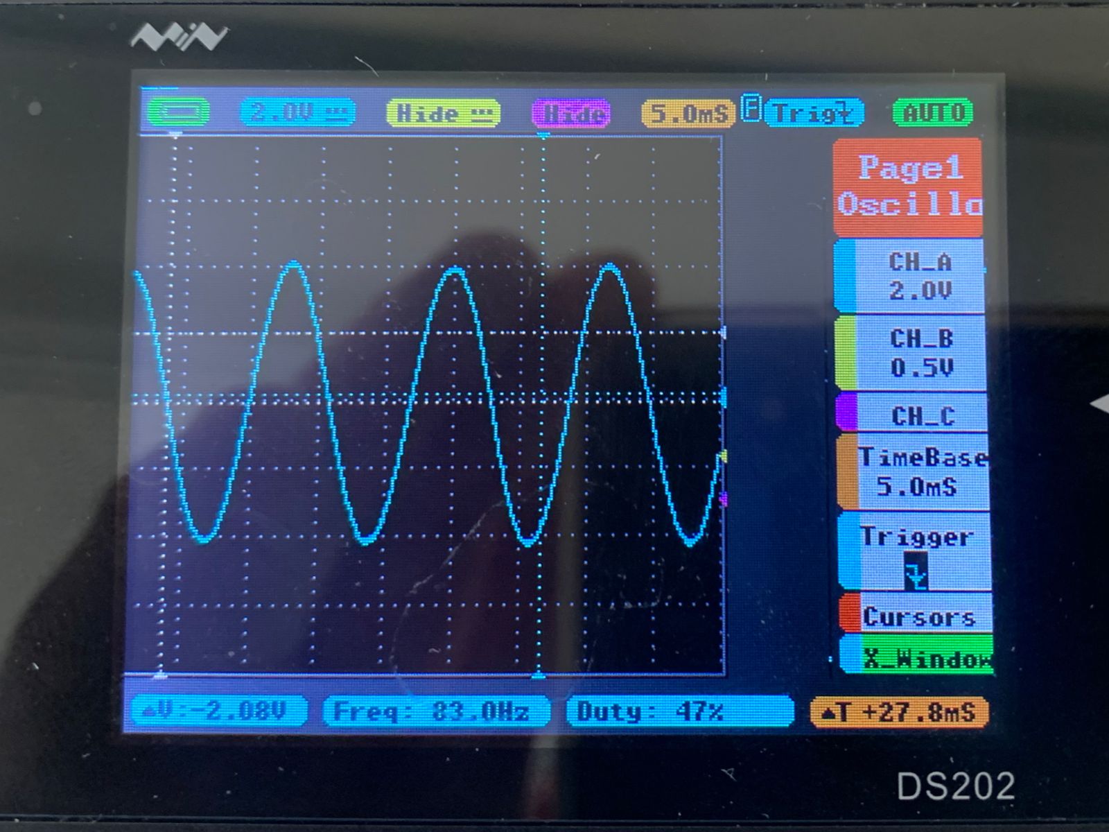
I managed even to read the RPM using the interrupt from the zero crossing detection, when each of the the commutation step happens. I used the Gyver-PID library.

But... still.. even being able to tweak the code, I can't get to less than 4-5K RPM in my motor. When I decrease PWM switching to a certain limit, the motor stops. As there's not Back-EMF anymore available to keep the commutation sequence.

But I know the motor must generate Back-Emf at 2K RPM because the original driver did it and the motor could run at 2K RPM normally with high torque (PID) (so it would mean 5% of the max PWM, or max speed).

So I 'm trying to figure it out why I can't get lower than 4-5K RPM with my "own" driver and software.

Things that I've tried so far:

Instead of 33V, I tried to run the motors at 18VDC. It made no difference at lower speeds, just the max speed is not 40K anymore (as expected).

I tested decreasing the input voltage because with one of the chinese all-around controllers, when I decrease the input voltage for the motor, the max speed decreased (as expected) but the lower speed also decreased to even less that the 2K RPM needed. (so it seems the 10% limit is mantained, but based on a lower voltage)

But even then with PID I had almost no torque at this lower speeds. The response to change in PWM is slower in these drivers ready-made drivers I tested, to make fast PID work.

The Simple-Circuit code I adapted to my DRV8302 board has the switch PWM frequency set to 31Khz. So I changed it to 62.5k Fast PWM, and noticed no difference. Even the (small) noise was the same.

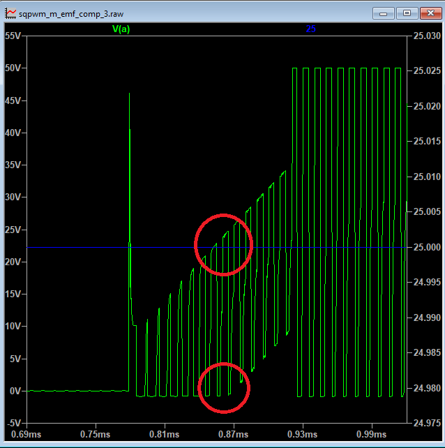
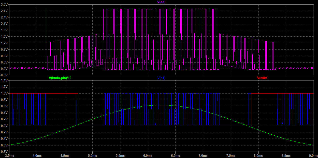
The Back-EMF in this development board is filtered and buffered and then I fed the 3 signals and a Virtual Neutral, reconstructed with the 3 filtered and buffered Back EMF and 3 10k resistors, into the external comparator, as in the Simple-Circuit schematics. A LM339 comparator is used.

So the 33V DC for the motor gets to 2.6V at the BEMF A, B or C connection pins on the DRV8302 board. Could this decreased voltage get to a point where it's no more being "sensed" on the comparators?

Could the fact that the Back-EMF, by being filtered, buffered and scaled down to less than 3V in the board, makes it's generated signals slower to be detected?

I even tried to read the Back-EMF signals "raw", by connecting them directly from the motor, with voltage dividers, bypassing the filtering and buffering steps. But then the motor rotates with a lot of noise and not smoothly, and also, don't get to slower speeds. In fact, doesn't even rotate properly. Maybe too much electrical noise from the switching PWM mosfets.

I'm running out of ideas on what to do next.

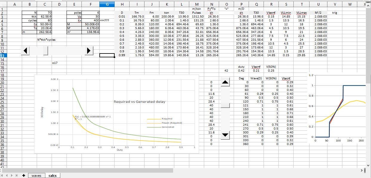
I always read that lower speeds can't generate Back-EMF. But how much in fact is a lower speed, for any motor? Is there a relation to top Speed? Can I calculate it? Can I make it's detection better?

Is there a way to improve the readings of back-emf at lower speeds? By lower to me I mean 2K RPM, in my case.

Thanks for reading this long post! If any more info is needed, just ask!

1 Like

How low of a switching frequency is the lower limit?

I'll measure with the scope. But when I get to, in PWM values, below 25 the motor stops. I did a workaround to actually make it work better in low speeds.

I set and increase a "delay" in the interrupt routine code below:

// pin change interrupt 2 (PCINT2) ISR
ISR(PCINT2_vect) {
  if ((PIND & PCMSK2) != pin_state)
    return;
  // BEMF debounce
  for (byte i = 0; i < 15; i++) {
    if (bldc_step & 1) {
      if (PIND & PCMSK2) i -= 1;
    } else {
      if (!(PIND & PCMSK2)) i -= 1;
    }
  }
  bldc_move();
  tacho.tick();
  bldc_step++;
  bldc_step %= 6;
  stall_counter = 0;
  delayClocks(cycles);
}
void delayClocks(uint32_t clocks) {
  do {
    __asm("nop");
  } while (--clocks);
}

At higher speeds (higher than 6k-7k) this delayClocks value is 1.

At at lower speeds, lower than 6K RPM, if I increase this delayClocks value, up to 2000, the motor gets to lower speeds without stopping, (Safely at 4K), the noise get's even better (I can't barely hear the motor wortking), current draw is minimal (10-20mA with no load). And if I increase this value to close to 8000-10000 I can get almost to 2K RPM, but then, it's not stable. If I touch the tip of the spindle it stops. And I'm not being able to set a Speed PID to keep this low speed under load. In facet, I don't know if Back-EMF is gone and it's switching like a stepper. I think not, because the motor runs slow and very silent, and draw minimal current...

I think this timing delay I'm adjusting on the fly, is that 30 degree difference between the zero crossing event to when the switching should be done. But I might be wrong.

I really don't know much about it, but if it stalls at the 25% duty at 31kHz, your pulses are 8us wide. Maybe a 16us pulse at 16kHz would perform differently?

Hi.
Let's start from the hardware.
There are 2 types of BEMF voltage detection> during PWM On time and during Off time>


The upper circle shows On time detection.
When the motor goes to high speed, the On time detection is more stable, because the pulse has more width. The opposite happens with Off time detection, which is good for low speed.
It is not clear what strategy is implemented in your board, but the posted circuit uses On time detection> good for high speed.

Thanks! I'm using exactly the same circuit schematics. The difference is that the HIN Pins from the schematic goes directly to the INH -ABC pins on my board. The same for the low side pins.

How could I adapt it to sense the off time detection also? Is it possible to have both circuits at the same time, using maybe another comparator (LM339) and another BEMF input pins on the Pro Mini?

Thanks!

Here is more clear what is going on, you can see the detection pulses.

About the BEMF voltage detection during Off time STMicroelectronics has a good application note with HW explanation basically an offset to OpAmp.
Also, there is a trick in the code you have posted how the (30 degrees) delay is calculated.
I'll check my notes from long time ago, I am sorry, could take a day or two.
Cheers.

cd00020086-sensorless-bldc-motor-control-and-bemf-sampling-methods-with-st7mc-stmicroelectronics.pdf (653.2 KB)

There are 2 problems here: the time delay and the PWM Off time zero crossing.
The code from simple-circuit senses the both, On and Off times, in alternate way. But is not clear what is the velocity constant Kv of your motor. Here is how the code works and how the delay must be calculated:


Frequency of the motor:	
Fm = D*VP*KV*poles/120 = D*Vp/M		: M = 120/(KV*poles)
									: M = 60/(KV*ppairs)
M – Motor constant. It has dimension of Volt*seconds.

Period:			Tm = M/(D*Vp)

Required delay after zero crossing:		30°/360°=12	

delay = Tm/12 = M/(12*D) = M’/(D*Vp)		: M’=M/12

M’ – Volt*seconds for the 30° delay after zero crossing detection.


Delay with loop:
The loop is in the ISR of the comparator. The loop is running when the comparator output is high during rising BEMF voltage or when is low during falling BEMF voltage. The counter variable increments by portions, proportional to the PWM duty cycle. Wider PWM - faster loop.

		For ( i=0; i<N; i++){
If(rising_bemf){
				If( !ton){  i-=1 }	// comparator out is low
			}else{
				If( ton){  i-=1 }	// comparator out is high
				}
}


Loop maximum time:		m = N*ticks*Cycles

Loop is counting (up) to N only during ton on rising and during toff on falling BEMF. The counted PWM pulses will be:
				Pc = m/ton		Pc = m/(D*Ts)

The estimated time of the loop is:
				dt = Pc*Ts = m*Ts/(D*Ts) = m/D

The required delay and the time of the loop must be equal: 	delay = dt

M’/(Vp*D) = m/D	m = M’/Vp


Here is one of my calculators:
ESC_30_delay_arduino.zip (27.0 KB)

The next step could be little changes in your board.
Cheers

About the calculator.
Change "cycles" cell and adjust N by the slider:

HI!!

A lot of info for me to digest!! I've been reading the stmicroelectronics PDF you sent...

I have some info and a lot of doubts so far...

Maybe the original controler was set this way.. reading the back-EMF in the PWM -OFF time. Because at the 33V supply it has, the motor runs at 47K RPM. And the motor's old controller is limited to 40K RPM max, so I guess, as the PDF says, the Off-time method is not good at Max Speed and Max PWM, because there won't be an off time to be detected to read the Back-EMF. So it's max allowed speed is not the MAX PWM to allow some room to read the Back-EMF at 40K. Does it make sense?

I'll have to study the code you sent... on how to adapt to the simple-circuit's code...

I don't know my KV of my motor... But I know it's top voltage, internal resistance, and pole pairs...

Doing this math: RPM = KV.Back-EMF (that can roughly be changed to VCC), so my KV would be something like 1424. (KV = 47KRPM/33V) Is that correct?

I tried slower frenquencies (like 8Khz) and nothing changed, except being noisier and rougher. Is it ok to keep the Arduino pwm frequency at 61.5Khz, and not at 31Khz? Is it better? My development board can handle these higher frequencies.

Hardware speaking now..

Also, by reading the PDF, it seems that I only need a series resistor (to decrease the current) directly between the phase (A,B and C) and the comparator? There's really no need of a voltage divider neither a capacitor (filter) on each phase?

Also, what's that voltage zener clamping diode for? Is it a 5V zener? You just connect it between GND and the positive of the comparator? Or is it a part internal of the ST7MC and not needed for my LM339 comparator?

And that D2 diode? Do I have to implement it also? Or in my DRV8302 chip it already has it internally? Or is it the N-Mosfet body diode?

The negative pin of the comparator I read that should be a low voltage, like 0.35V to compare with the voltage from the A,B or C. Is that so? In the diagram it's not connected to anything...

I'm trying to figure out how to adapt my hardware...

Thanks so much for all your help!!!

It is fun for me : )
Can you please run the motor with a drill and measure the frequency and the (phase to phase ) amplitude with oscilloscope? Kv can be calculated that way . It is good to be sure.
Probably just increasing the 10kΩ to 20-30kΩ could help, but please don't do that before you are sure that the timing in the code is ok! Also, reducing the values would require clamping diodes to somewhere.
ST uses ADC, not comparators.
Cheers

Ok.. I used a driller. My Scope is a hobby 2 channel one... and I'm still new to it..
:grimacing: Does it help?


I'm sorry, but I didn't get the rest you said... Increase which 10k resistors? Those in the virtual neutral in my schematics?

Also.. is there a way do this PWM-OFF using the LM339 comparator (instead of an ADC) I already have in my protoboard??

So many new things for me... :slightly_smiling_face:

Thank you! It helps raising questions : )
Don't worry about the comparators for now, you can achieve low as 20-30% with your current setup.
But this is what I calculate:
image

Means that your motor can't go more than 18000 RPM at 30V with estimated Kv of 200. Can I have the model of your motor, please? May be I am calculating something wrong.

Sorry, you said 6 poles pairs, my mistake:
image

Still, please say the model of your motor.

Hi! I tried to disassemble it, but couldn't make it all the way to check if it's really 6 pole pairs. I have another one, of another type (rated at 48V) that when I opened I saw 12 windings around the spindle). Then I assumed this one is also the same, as they are both for the same use, same speeds, but different brands.

But I can confirm the motor is rated at 36V... it's written in it's outer case:

Magnets define the poles, not the slots. The slots will be anything that is divisible by 3.
And that's my problem, I can't figure out how many poles there are in the motor.
For example 8 poles and Kv=100 gives the same speed as 16 poles with Kv=50. Can you please rotate the motor in hand trying to count the resistive ticks for one revolution?

Is feedback really required for slow speed? Isn't the speed then determined exclusively by the pattern shift frequency, like with a stepper motor?

Ok! I’ll try that later tomorrow! Will let you know.

I was reading about this: Would it help to do the same running the motor with an electric screwdriver to get the frequency and amplitude, but also know the exact speed with a tachometer? I can also do that.

Also, if it helps also, in the simple-project code, I measure the RPM using the modified tachometer lib and compare with a real tachometer. To make RPMs match, I must count the interrupt tick() (that goes into the tachometer RPM library formula) one time each of the 6 commutation steps. Or divide the algorithm for calculating speed by 6. Does that mean that it needs 6 steps for performing a mechanical revolution, besides being an electrical full revolution?

I get this on the tachometer.h: i use this way if I count one tick() each time the 6 commutation steps are done:

 // get rpm
 uint32_t  getRPM () {
 return  getTime () ? ( 60000000ul / prd) : 0 ;
}

Or I change into this I If I count the ticks each time the interrupt comparator is valid and perform a single commutation step

// get rpm
 uint32_t  getRPM () {
 return  getTime () ? (( 60000000ul /6)/ prd) : 0 ;
}

Oh, you said that with my setup I could get 20-30%… of what? Max speed? PWM? In terms of speed, I need to go lower than that. I need to go to 5% of 40K, what would be 2K. I can get to 20% (8K) normally so far…

Thanks!

1 Like

Hi!

Well, i sure can run in a predetermined timed step switching pattern, but it’s not a smooth, silent, rotation… and I need also to be able to increase quickly and smoothly and silently to higher RPMs if I turn a potentiometer, for instance…

The startup sequence is indeed something like that: a timed switching pattern that goes faster and faster until it has enough speed to Back-Emf takes over.

Rodrigo