The PI control is more likely to smooth the transition when changing the speed. After all the bldc is a synchronous motor, it will lose a cycle and will stop if the change is sharp.
I am afraid that 6 step control is not suitable for 5-10% pwm (mean speed). For servo applications there is Field Oriented Control, basically measuring the current, converting the 3 phases (values) to DC equivalent with Clarke transformation, then Park transformation, etc maths. For FOC every parameter of the motor must be known in advance and I am not sure if Arduino is capable to do this.
Still, depends from the motor, with 6 step control could be possible to reduce the lower speed but losing the higher. Sorry.
Yes… foc is not an option and I’m pretty sure it’s own old driver is not using sensorless foc… because even foc cannot get to these higher speeds…
But how much of the top speed would I lose implementing the off-time pwm method?
Because if at 33V I get 47K RPM (no load), I can lose this top 7k and stay in the 40K, so I wouldn’t be at top speed…
I would like to give it a try in this pwm off-time, if you can help me out… ![]()
Ok.. Things that I've tried now...
Rotate by hand gives not even a single click....
Put an iron screwdriver in the outer casing to "sense" the magnetic poles when rotating didn't work also.. Didn't use a neodimium magnet, although I have plenty of small ones.
I shorted two phases of the motor and rotated it by hand and not a single click. It offers just a little bit more resistance, but not much, but the spindle doesn't stop at any particular fixed place.
I put 3V and 50mA between two phases, with a current controlled bench supply and rotated by hand the spindle... it's weird, but it seems that when I try to rotate the spindle, it seems that there's only two poles... It rotates 180 degrees to a more or less fixed position and then more 180 degrees. I was afraid of using more voltage and current.
Any more ideas?? ![]()
![]()
Hi again... I was testing my other motor (48V one) that has it's own driver and look what I've discovered:
I can digitally set the desired MAX speed on it's touch panel. And with a pedal I can control the speed from zero to this max set speed. So I thought it worked this way... but... In reality this is what happens:
If I set the max speed to 5K RPM, I can go from 2K to 5K smoothly, with strong torque (PID) .
If I set the MAX speed from 6K to 9K, I can got from 2.8K to the MAX speed. So I can't anymore get to 2K min.
But If I set the MAX speed to 10K RPM, the min speed is 10K and max is 10K, so it works as an ON/OFF button. If I set the MAX speed from 10K to 40K, the min speed is always 10K!
So I guess there's this PWM-OFF Back-EMF Strategy at these speeds lower than 10K. And when set from 10K to 40K, it's just the settings I already have working, PWM-ON Back-EMF sensing...
So... I guess I'll I won't be able to cover all the speed range with a single setup..
But I could have both setups, and choose one of them depending on the max speed settings. Is it possible?
I'll do my best. If I had the motor I would reverse it to the quantum level. Unfortunately I have to deal with simulations. What I did so far:

Can we go the other way please, run the Arduino code and try to get 1 full step with your scope. I want to see how symmetrical is the detection and what is the ringing on the phase lines. If you can catch few pwm periods also will be nice.
I know exactly how important is the low speed drilling/milling when it comes to plastics.
![]()
Ok!
Newbie (me) question: How do I connect the scope while running the motor on the arduino? Connect scope probe to any of the 3 PWM active arduino pins (Pins 9, 10 or 11) and ground, while running? Or directly to the motor (set the probe to 10x) ? Won't I fry the scope? ![]()
![]()
I think yes.
What I see is DS202 scope, right? With probe (x10) is ok:
User Manual V1.0
3
■ Analog bandwidth:1MHz
■ Max sample rate:10MSa/s
■ Max sample memory depth:8K
■ Analog input impedance:1MΩ
■ Max input voltage: ±40V( X1 probe) <<<<<<<<<<<<<<<<<<<<<<<<<<<<<<<<<<<<<<
■ Coupling:AC/DC
■ Vertical Sensitivity: 20mv/Div~10V/Div (stepping in by 1-2-5mode)
■ Horizontal sensitivity:1uS/Div~2S/Div(1-2-5stepping)
A or B or C phase to GND
Connect the scope before running, one of the wires to the motor to gnd. Adjust probe x10 before you run the motor.
Yes please! My calculations still doesn't match.
Maybe there is a gear box inside the motor? You have the perfect idea already: measure the RPM's with tacho and simultaneously the generated voltage and frequency with the scope.
Will do it later then the scope measurements, also with the tacho attached!!!
No gearbox, sorry. It’s direct drive…
![]()
Hi! Sorry for the delay... it's mother's day here in my country!
First two pictures are taken in 5100 RPM more or less. it oscillates a bit.. Second two pictures are taken in 10300 RPM more or less also.. Does it help ??


I'll try arduino running the motor later!
Thanks so much! ![]()
Regards, Rodrigo!
Can you show two phases in two channels at the same time?
For sure I can! two phases with the driller rotating the motor? At which speed?
Ok, here we go.. scope connected to one phase (1/10 Voltage setting) with arduino running the motor.
The scope graphs oscillate a lot, is not a beautiful square pwm.. i tried to pause the scope to take pictures in which I considered to be... a more... beautiful image... ![]()
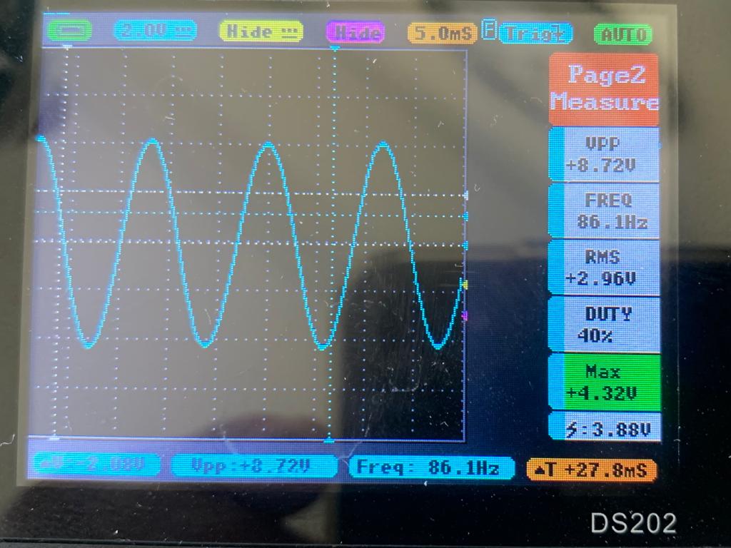
First: 34 pwm close to 10K RPM - no load

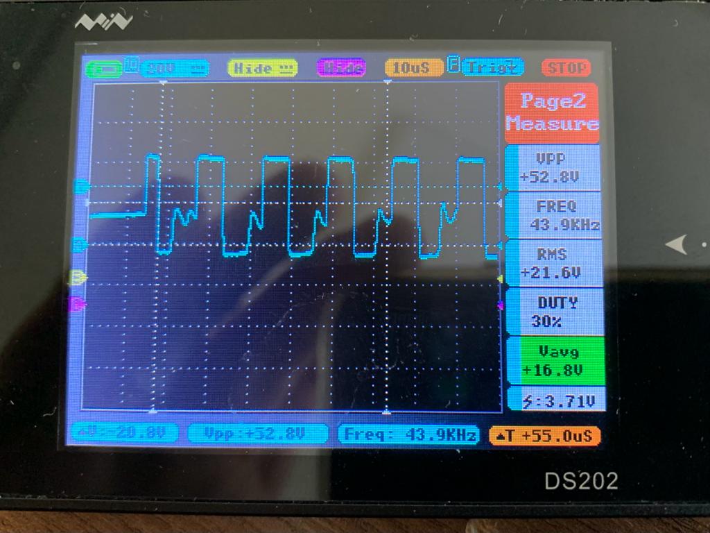
Second: 102 pwm close to 30K RPM - no load
Third: 166 pwm close to 40K RPM - no load

Fourth: 255 pwm close to 48-49K RPM - no load

I was getting lower RPM readings some days ago because I attached a handpiece to connect a bur to be able to read the speed with the tachometer before... and this this handpiece acts as a kind of small load. Now I took the measurements of the motor in no load. the RPM was measured within the arduino.
Does it help??
And how do I connect the scope probes. One probe goes to phase A and B. And the other one? I connect to phase C .. and the other wire?
Both to the common supply GND (-), the signals from A and B. Without a PSU GND and no star connection of the phases chose one phase for the GND and the others for signals.
Ok, I think we are almost there with the motor. I had the mistake using Vpp instead Vpk in the calculation of the Kv.

As you see with 10% PWM duty the RPM's are 5k. So, decreasing the PWM frequency may help to get lower speed.