Ok, so my motor has in fact only one pole pair? So designed for high speed.. How wrong I was... but even so, in the original driver, when set at 2K RPM it run with strong torque...
I even got to slower speeds than 5K... but I had to increase that delayClocks value a lot. To get from pwm 26-25 to until 20 I guess, I had to increase that value to 2000.
The min I got the motor spinning is at pwm 15, with the motor at close to 1000 RPM (with a value of delayClocks at more than 10000), but then, serial.printf's data locked, stopped being printed in the monitor, like the code was stuck, RPM's were not read anymore by the code... but I could check with the tachometer... it seemed more like a fast stepper, so I don't know if Back-EMF was playing a role in a guide for the motor spin. And if I touched the spindle it stopped.
It seems that by adding this delayClocks() higher value, I artifically decreased the PWM frequency?
I tried changing the pwm frequency of the fast-pwm to 1/8 scalar (61.5khz / 8 = 8Khz) , but I couldn't get to lower speeds. In fact it got worse noise and it didn't improve anything related to speed..
I can try other frequencies... just tell me and I test it!
I think that there'll be a setup for higher than 5k RPM, and an off-time PWM setup for lower speeds. Do you think it could go to 2K in this off-time setup? I believe the way it is now, we won't achieve lower speeds...
There must be a way because the original driver does it... Damn it!
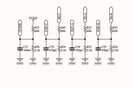
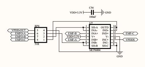
Just for adding new data, this development board has the three back-emf signals filtered, the voltage is decreased to 3.3V acceptable levels and is buffered. This is how it's done below:
Here the signals are brought to a safe voltage and filtered:
And here they are buffered (why is this buffering needed anyway?)
So you can see that there's no Virtual Ground output pin directly from the board. I had to create it externally with 3 10K resistors using EMFO-A, B and C pins. So the Virtual Ground I created after the leveled down voltage and after the buffering. Don't know if it affects anything.
But there's the VPDD-OUT, which is the bus voltage output, also decreased to the same levels and buffered.
I tried to use this VPPD-OUT divided by two (a voltage divider with 2 10K resistors) to feed the comparator inverting pins, instead of using the created virtual ground to feed those pins. it simply didn't work with the code. The only way it works is to create the virtual Ground between the three phases. Why it didn't work? Should VBUS/2 have the same effect of the Virtual - Ground?
Blockquote
Both to the common supply GND (-), the signals from A and B. Without a PSU GND and no star connection of the phases chose one phase for the GND and the others for signals.
Mine is star connection.. Couldn't measure both at the same time using a driller to spin it... I can connect both channels when running from the PSU-Arduino, with a common supply GND..
To run the motor at those low speeds requires some type of PWM cycling where the PWM is high enough to make the motor move a few degrees, then PWM needs to be lowered or cut so the motor does not run too fast. This is repeated in a very fast cycle and with the benefit of some rotating inertia the overall rotation can be smooth (or smooth enough) and a very low RPM can be achieved.
Can you put a scope on the original driver operating at 2K speed?
No... the minumum speed I managed to get, stable, is 3K RPM, at 16pwm, but I had to add 10,000 Delayclocks (I guess it's 0.6ms) after each commutation step, inside the interrupt code, to be able to get to this low speed. This is the graph at 3K RPM, 16pwm: (there's a small load in it.. the 1:1 handpiece that allows me to connect a bur to measure with the tachometer. At this speed, and maybe because of the delay I put in the interrupt code, the RPM code is crazy and gives me 4X the measured real RPM. It doesn't happen at 5K-40K RPM. But below that my code is not working well for reading the RPM pulses. That's why I used the external tachometer.
I liked what you said about variable frequency on the low end... do you think it would it be possible to adapt to my case?
I tried getting to 1/64 scalar on my FastPWM timers 1 and 2, but it didn't improve a thing... wasn't able to get to lower than I already get at 61.5Khz. And it's noisier and not stable.
Yes, one of the ideas I think must be tried. But before that I want to be sure that the timings are right. The comparator way is counting pwm ticks to get the delay with error dependable from the speed. Dynamically changing the pwm helps for smooth operation.
In my case, basically they said that to acquire such high speeds (40K) there would be a need for a really good CPU to do all calculations, so FOC in high speed is a no go.
And for low speed, which is what I want also, unfortunately, they don't have in their library (yet) sensorless FOC. So, there has to be some kind of encoder. They will (don't know when) implement it in the future, but for now, there's no FOC based on back-EMF, with their library..
I tried changing the "debounce time" - the value "20" in the for-loop in the Interrupt routine. I tried increasing it when I try lower PWMs.
For instance: I set the PWM to 20 and set the debounce value to 21,22,23.. 50... can't find a pattern that improves it...
I can only improve it so far, make it work quietly without stopping at speeds lower than 5-6K until 3K RPM by adding a delay (inside the Interrupt) after each step of the commutation is done. This improves a lot in lower speeds, and make it possible so far..
// pin change interrupt 2 (PCINT2) ISR
ISR(PCINT2_vect) {
  if ((PIND & PCMSK2) != pin_state)
    return;
  // BEMF debounce
  for (byte i = 0; i < 20; i++) {
    if (bldc_step & 1) {
      if (PIND & PCMSK2) i -= 1;
    } else {
      if (!(PIND & PCMSK2)) i -= 1;
    }
  }
  bldc_move();
  tacho.tick();
  bldc_step++;
  bldc_step %= 6;
  stall_counter = 0;
  delayClocks(cycles); // Increasing  cycles (a lot ) makes 3K-5K speeds obtainable...
}
But then, I'm adding a long delay inside the ISR... I guess it's not a good approach...
In the code linked in #45 I set a threshold between the normal fixed-high-frequency/variable pulse code and the fixed pulse-variable frequency code. I really don't know much about your system, but when you get into needing the large delays, maybe switch from the delays to a different mode, scheduling a one-shot or interrupt to handle the post-delay work instead of handling all the timing within the interrupt.
Ok... I'm checking your code... But I would need Timer 1 and 2 (3 PWM pins) to behave exactly the same at the same time with the same values... This library only works with Timer1.. It would have to be adapted to use Timer2 too... tough job!
(edited - I had something wrong with my probe and I replaced with another one)
Hi DaveX!
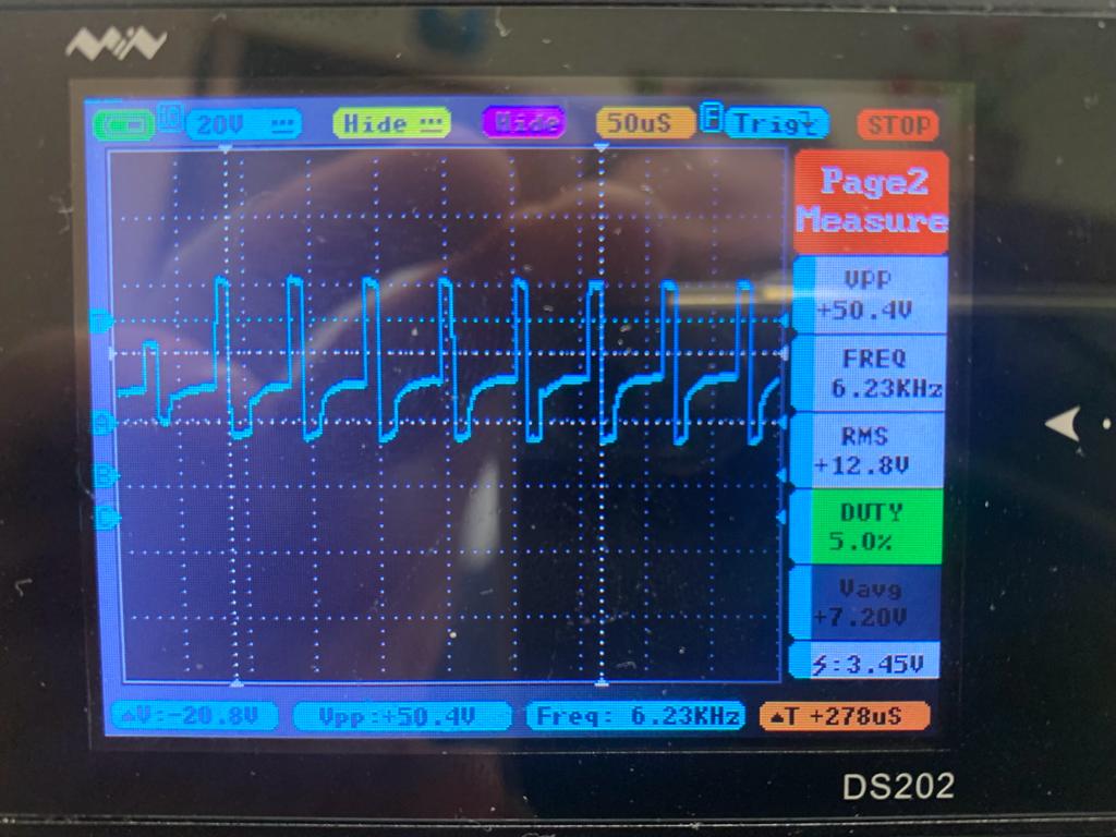
I didn't pay attention to your question... You wanted the Original driver, not the driver I'm trying to assemble. So I got the original driver wired (in the original, the speeds are fixed. I can't continuously vary their speeds. I set one speed and can only turn on and off. So this is how it works at 2K RPM, 3kRPM, 5K RPM and 10K RPM and the last one, a comparison between the original driver at 3K and mine (with that long delay inside the ISR to allow that speed to "happen". The Supply is DC 33V for the original driver, the same I'm using for my project.
Thanks. I was curious about what the original did with the frequency and duty cycle at the working, low, RPMs while still torquey.
rpm
freq
duty
pulse width, calc'd
2K
4.03K
3.0%
7.4us
3
5.19
2.0
3.9
5
5.62
2.0
3.6
10
6.23
5
8.0
your 3K
62.9
7
1.1
These are speed controlled and unloaded, right? So they wouldn't really need much energy to maintain unloaded speed. Does the 2K ramp up the duty cycle under load?
Exact. Only the load of the handpiece attached to it, running with no "extra load". And in fact, that 2K speed is really 1600RPM, measured with the external tachometer. So now below: