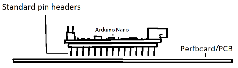
If you lower the Nano so that the pins stick out the other side in the image, can you just solder those pins directly to the perfboard? I mean, I want my project to be permanent, so I can do this, right?
Why do so many people use 2 pin headers to do this? I understand I guess if you want to take the thing out, but, I just like the idea of making something permanent by soldering it and not hoping the Nano will stay put in the second header (I'm sure they would, I just don't like the idea of it much.)
Now, look at the ATMega here. I'm assuming it's not just placed onto what I assume to be headers there, correct? I assume the ATMega is soldered or something to them? If so, how did they do that? You obviously can't fit anything through those gaps.
If you can answer these questions I'd be very grateful For some reason I've been struggling to figure this out 100% for the past many days.
It sounds like you got it mostly, the only thing you didn't take into account for the permanent setup is do you want the long end of the pins going through the PCB or sticking up. In both cases, you will probably cut the excess off. If instead, you choose what you call the non-permanent option, all the pins are the right length. In many cases, this is preferred in case the Arduino goes bad.
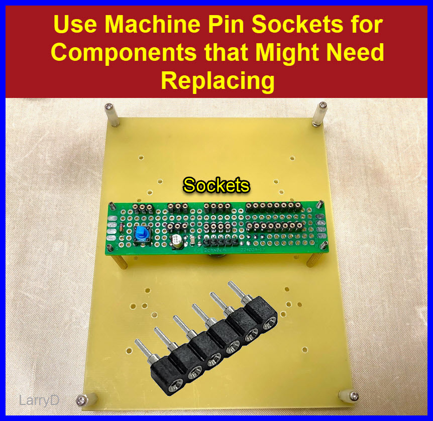
In the case of the ATMega, no, it is not soldered. Those are industry-standard sockets. There are likely billions in the world already. Almost none ever fall out; in fact, it's difficult to insert and remove them.
Ok, thank you! I have a couple more questions then.
What's the difference between a socket and a female header? If I just connect the Nano to a female header, how stuck on is it really? Can I stick a Nano into a socket? Sorry for the batch of questions.
And for the first part of what you said, I assume you always want the short part of the header going into the Nano, and the long into the PCB. That's how I've always seen it anyways. Thank you by the way, this was very helpful
A socket is what you showed in the last picture of the ATMega. The thing that plugs into it has much larger blade like legs.
When something like a NANO is inserted into a female header, we have to either use a tool or at least lift one end up then a series of rocking motions will remove it. It does NOT come out easily.
You don't have to solder everything. DIP (dual inline package) chips in sockets is just fine. Resistors and leds work well in sockets but capacitors tend not to.
Arduino Uno has the 328P in a socket just so you can remove and replace the chip. Maybe you burned an IO pin and it's cheaper to replace the chip than the whole board.
The main reason is so you can develop with the Uno then pry the chip out and put it in a PCB socket or not.
Many chips are not DIP but rather surface mount (like on every Nano I have ever seen) which is very advanced soldering to say the least.
An ATmega328P DIP chip has 28 pins but they are flat. Put one in a 40-pin socket and you have 2x6 holes for connecting including jumpering to.
Telecommunications splices for thin wires drive a steel blade through the wires making contact with all of them, then the good ones flood the join with silicone to seal them. You can buy wire splices by the box and they get down towards 25 cents each. No solder at all.
You can get DuPont cable with one or both ends "sleeves" that slide onto pins and they work well.
But if you want to solder to a pad or trace on a board, take care you don't burn the epoxy holding it down (be quick) and first "tin" the parts you would join and then solder.
Youtube has plenty of videos on soldering, watch some of those while looking for differences and sames.
I used to replace PCXT 8088 CPU's with NEC V20 CPU's. The NEC chips did memory addressing faster than the Intel chips so for about $10 I could speed a PC up about 15%.
Often I have upgraded socketed CPU's to faster ones but CPU sockets changed in the 90's.
Solder what you need to. Go with connectors when you can.