I need to measure a PWM-Signal that comes from an Electric Vehicle Charge Control.
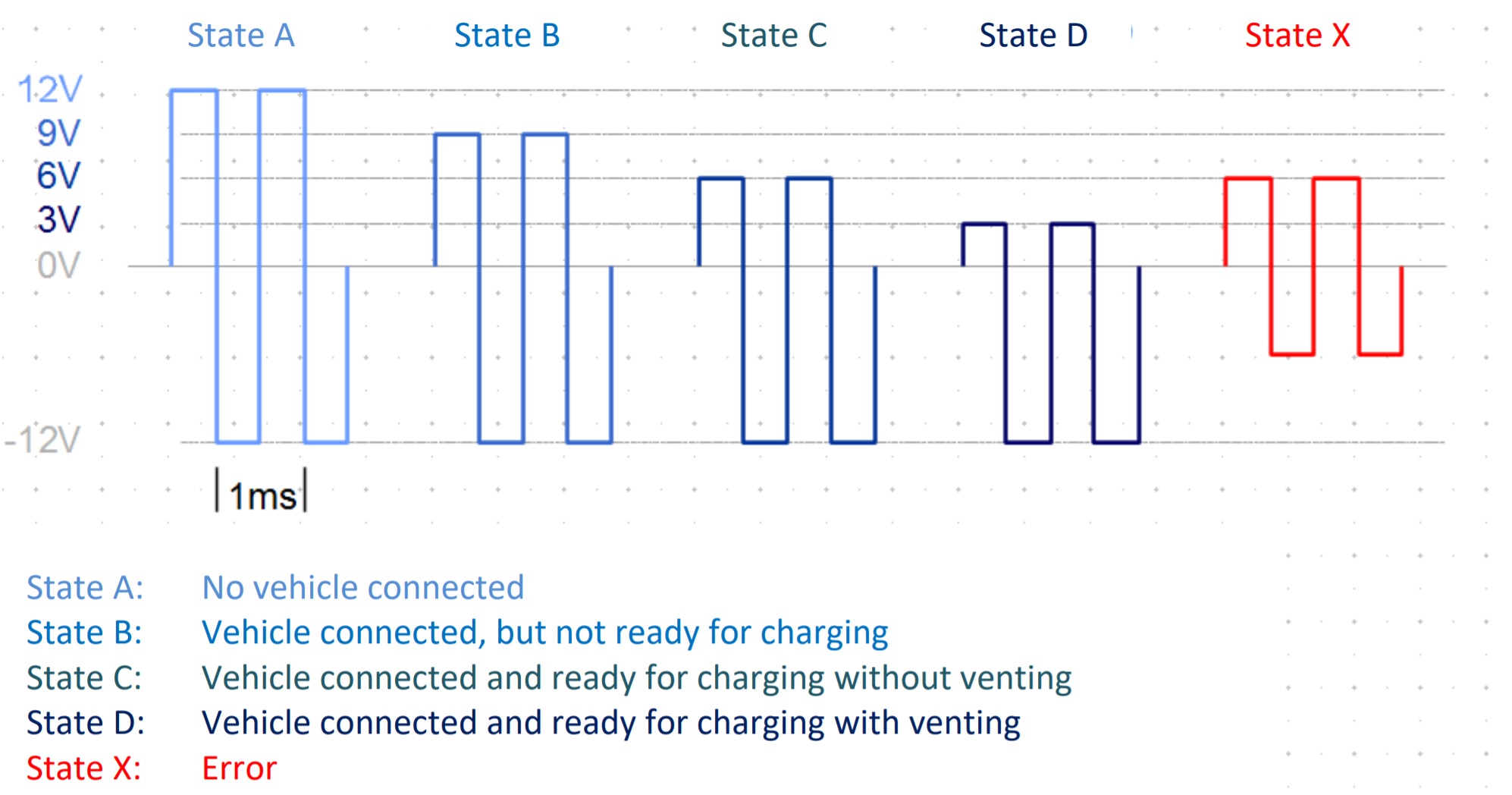
The PWM-Signal looks like in the picture: PWM-Signal.
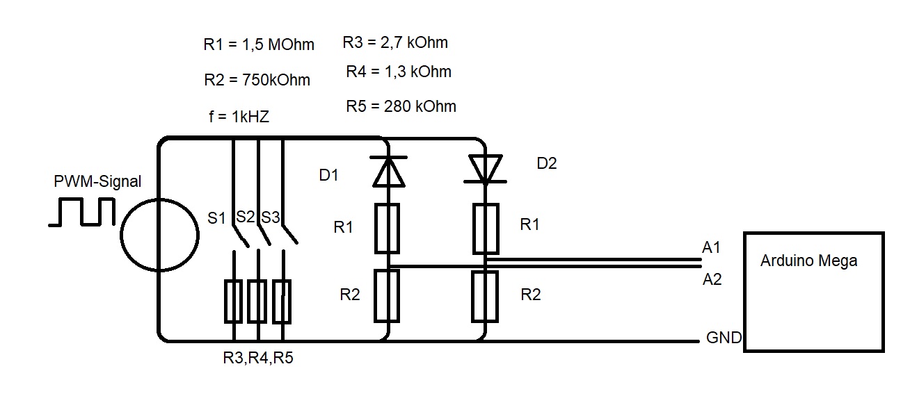
Depends on the Status and the Resistors an the end of the electric circuit the upper Voltage changes from 12V to 9V to 6V and to 3V. ( Pircture: Circuit)
S1, S2, S3 open should give me : 12V / 0V
S1 closed , S2 open, S3 open should give me: 9V / -12V
S1 closed, S2 closed, S3 open should give me: 6V / -12V
S1 closed, S2 open, S3 closed should give me: 3V / -12V
With the Ltspice Simulation everything works fine.
I can measure the upper voltage but I cant get the lower voltage.
I also cant get the frquency by using pulseIn()-function.
This one is the official circuit.
I just want to measure the EV Side. (Voltage and Frequency)
The voltage divider at the previous schematic is because the Arduino cant measure voltages above 5V and the diodes were to let through the positive and negative voltage.
Oh I see. Ok.... thanks. Maybe you are right.... voltage divider to reduce the voltage down to some manageable level ... such as +/- 2 volt. And then into a unity gain buffer, and apply a DC offset to get the voltage to be entirely positive, so that that arduino can take some measurements.
What's the time scale of your graph there? Time scale.
Hi All,
I must be missing something here. The wave forms indicate
that they are generated by a (split) +12v and -12v power supply
but the diagram showing how the signal is used shows only two
output terminals! That indicates that the output is uni-polar, doesn't
it? The world does not see the mid-point (0v) of the power supply.
So there is no minus voltage peak to measure. We should look only at
the peak-to-peak instantaneous voltages.
Herb