How to setup a 2N3904 Transistor with Arduino?

Hey everyone!

I hope that you've been having a wonderful day so far.

Capture

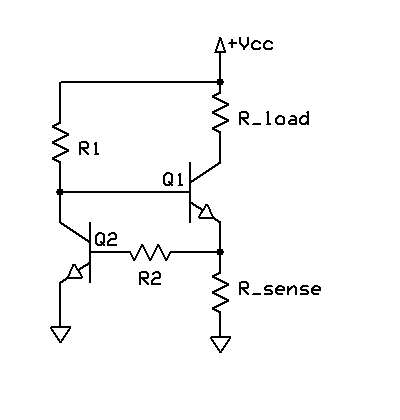
As you can see in the attached picture, I am connecting the output pin of my Arduino to a 1K ohm resistor which, in turn is connected to the Base of the 2N3904 Transistor.

Suppose that I want 10 mA to flow into the load, i.e. the "blackbox" connected to the Collector of my transistor.

I am having a difficult time understanding the datasheet.

Your help would be much appreciated.

More to that, if the GPIO's voltage is +5V, will there be current flowing from the 5V source attached to the Collector into the 1K resistor attached to the base? (I'm thinking of that because both of them will be connected to a +5V source so maybe that could happen, i really don't know)

Thank you so much in advance!

Do you happen to know the resistance of load?
Pins will send a PWM signal. So the average current can be kept close to 10mA if you know the resistance of load. But the actual current will be either 0 or (V-0.1)/Rload.
And you might need a smaller resistor there...

Thank you so much for your answer!

My load is a PIN diode whose forward voltage is 0.89 Volts.

That's all I know about it.

Can this help?

If so, can you please provide me with an explanation on how to choose the correct values of the resistors connected to both the base and the collector of my transistor?

I really appreciate your help and efforts, thanks again!

That makes things more difficult. You will need to add a current limiting resistor in series with the diode.
Say 200 ohm.
Imax = (5V - 0.89V - 0.1V)/200
But you may also not use pwm and calculate the resistor...
R = (5V - 0.89V - 0.1V)/(10 mA)

Google current source.

A basic one will be similar to this:

image

As well as the above in @build_1971 's answer , you are trying to use the transistor to provide an exact amount of current. To do this you need to know the "gain" of the transistor, sometimes called in the data sheet as the Hfe.

The thing is that this parameter has a large spread, that means the gain can be different from transistor to transistor, so you can't work out what value to make the base resistor.

Not actually knowing what the load is nor how much current it needs makes it impossible to calculate the base resistor. Basically no one uses a transistor like this, the are normally used as a switch, not a linear current device.

In the data sheet is an Isat (current saturation) value and you use that to find a base resistor to turn the transistor fully on.

Hopefully you know what you intend to use it for - and that information would let us give you more targeted help.

Applications of PIN Diode

PIN Diode has a wide range of applications coming in various fields of physics like radio frequency switch, microwave switch, radiofrequency attenuator, microwave attenuator, photodetector, etc.

Is this a school type project where you are learning about Ohms law and the voltage drop across silicon junctions, saturation of transistors etc. or has this some more practical application ?
For learning about the behaviour of analogue circuits or components, some simulators can be useful e.g. LTspice, however, these also have a "learning curve".

If you are looking at the data sheet of the transistor, and since this appears to be a switching application of the transistor, the graph "Collector Saturation Region" may give you some useful data for your calculations.

Hey again Everyone, I hope you're all doing great.

I'm still new to the world of Arduino, Shift Registers and MOSFETs. Hence, your help would be very much appreciated.

I have a project in which I have to control 170 PIN diodes of type SMP1345-079LF according to a certain pattern. Those PIN diodes, according to their datasheet, have a forward voltage of 0.89V. Also, to be properly biased, they need a current of 10 mA flowing through them.

This said, I am using Arduino MEGA along with shift registers and MOSFETs to do the job.


In the diagram above, you can see a sample of how I am planning to do the connections.

When the PIN diode should be turned ON, the Shift Register will give a voltage of 5V to the gate of the MOSFET and, after that, a current Id=10mA should flow into the diode. (I'm pretty sure I need to add a series resistor with the diode here. Again, your help would be extremely appreciated).

I have previously thought about using the NPN transistor 2N3904 instead of the MOSFET, but since its gain (beta) varies between 100 and 300 at Ic = 10 mA. I decided not to opt for it.

Please, can you help me choose the appropriate MOSFET for my circuit?

Also, please do not hesitate to guide me if there is anything wrong with my circuit.

Thank you so much in advance for your time, efforts, and help!

Hello 6v6gt,

No, this is not for a school project. Actually, I am doing a project related to Radio Frequencies and Electromagnetics. This said, I have a metasurface composed of 170 unit-cells. Within each unit-cell, I have a PIN diode of type SMP1345-079LF that should be either ON or OFF. Each PIN diode is controlled individually.

For that, I am using an Arduino along with shift registers and transistors (ended up changing my mind and opting for the use of a MOSFET instead of a BJT).

I turned down the BJT option because of the gain variation (Beta or hFE). Indeed, when looking at the datasheet of the BJT, I noticed that for Ic=10mA, the DC current gain could vary from 100 to 300 which made me turn down that option.

Thank you for your help!

Hello Johnerrington,

Thanks for your response!

I have a project in which I have to control 170 PIN diodes of type SMP1345-079LF according to a certain pattern. Those PIN diodes, according to their datasheet, have a forward voltage of 0.89V. Also, to be properly biased, they need a current of 10 mA flowing through them.

This said, I am using Arduino MEGA along with shift registers and MOSFETs to do the job.

Hey Grumpy_Mike,

Thank you so much for your response!

As you said, "The thing is that this parameter has a large spread, that means the gain can be different from transistor to transistor, so you can't work out what value to make the base resistor."

This is exactly the reason why I have turned down the option of having a BJT.

I have opted for a MOSFET instead. Can you please help me with that?

Select a series resistor that gives 10mA.

Oops, you can only drive 6mA per output.

This would be a much better choice:

Hi LarryD,

Thank you so much for your help. I really appreciate it.

The problem, I believe, in the design you're proposing is that when a current that is "high enough" is sourced from the output pin of the shift register 74hc595n, there would be a "Voltage drop".

Indeed, the output voltage of the 74HC595 shift register depends on the output current being drawn from the device. In general, the output voltage will decrease as the output current increases, due to the internal resistance of the device.

The output voltage of the 74HC595 is typically specified as a range of values, depending on the output current being drawn.

Also, it came to my attention that the output voltage of the 74HC595 may not be well-regulated, meaning that the voltage may vary more than desired with changes in output current or other factors such as temperature. Additionally, the output voltage may not be well-matched between different output pins, meaning that there may be some variation in voltage between different output signals.

That unpredictable voltage drop makes the value of the resistor that is in series with the diode ambiguous.

Please correct me if I'm wrong, I'm still new to the field and I'd love to learn from you.

Thank you so much, once again, for your valuable help and efforts!

According to the datasheet, I can drive a current upto 35 mA per output pin for the shift register 74hc595n. I should however be careful not to exceed a total current of 70 mA for all the output pins together.

Besides that, while I really value your proposal of using the TPIC6B595 instead, the problem is that I have already purchased 22 74hc595n shift registers and I'm stuck with them now...

There's definitely a lesson to learn from that.

Thanks for your answer!

See the TPICB595.

The supply you use is connected to the resistor then to the anode with cathode to the open Drain MOSFET output.

My problem here, I believe, is not with the shift register itself but with the MOSFET.

I have got no clue of which MOSFET to use. There are tons of MOSFETs out there and I got confused.

Could you please guide me in the right direction?

Many thanks.

This I.C. has the MOSFET included in the chip.

The schematic shown has all the components in one package.

Do you think I should consult the TPIC datasheet to see what kind of MOSFET are they using?

Each output can sink 150mA, in your case, you only need 10mA which the series resistor will set.

VDS maximum is 50v, you are using only 5v.

The N channel MOSFETs in the chip have a low rds(on) of 5 ohms.

This is all you really need to know.