Thank you Larry,
Things are much clearer for me now.
Since I'm stuck with my 74hc595n shift registers, what MOSFET do you suggest I connect to the output pins of my registers to get the 10 mA that I need?
Thank you Larry,
Things are much clearer for me now.
Since I'm stuck with my 74hc595n shift registers, what MOSFET do you suggest I connect to the output pins of my registers to get the 10 mA that I need?
For a 74hc595n you can select one of the MOSFETs in this PDF.
Unfortunately most will be in SOT-23 package.
A IRLML2502 would work for example.
Suggest you charge buying them to educational charges ;) and get the TPICB595.
Thank you so much for the suggestions! I extremely appreciate your help and efforts ![]()
The IRLML2502 looks good, I believe that the next step would now be to run some simulations on it to really grasp the way it works.
Do you suggest any specific software for simulating the MOSFET?
I think PSpice would be good?
Thank you so much, once again
No, I don’t use a simulator, I use hardware directly.
Let’s assume you use MOSFETs:
Just remember, if you use 11, 74hc595n you need 88 external MOSFETs
Using TPICB595 you only need the 11 chips.
Why do we have two threads on the same project ? ![]()
Hi, @kwh05
Can you please tell us your electronics, programming, arduino, hardware experience?
I think you are OVER thinking your project.
Get out there and build something to check your parameters.
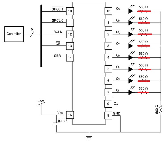
Build this, I'm not sure what your controller is.
Write some code, lookup the Library to control the 575 and use one of its examples.
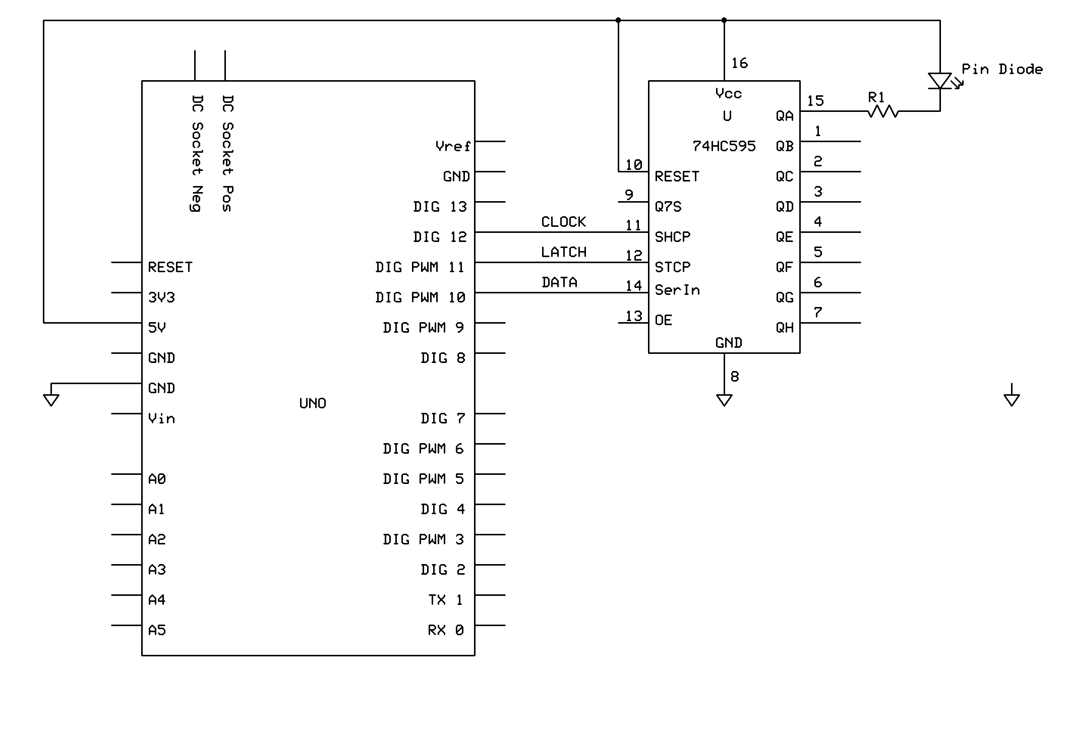
Volt drop across R1 == > 5 - 0.4 - 0.89 = 3.71V
For 10mA through R1
R = V / I = 3.71 / 0.01 = 371R
330R + 47R = 377R
Try that series combination of 330R and 47R.
Run that diagram and using your DMM measure the voltage across the combined 377R resistor.
Then use OHMS LAW to calculate your diode current.
We are at post #7, now build something and experiment.
Get the protoboard out and experiment.
You cannot go from theory/speculation to fully working prototype, it doesn't happen in the real world.
What are you expecting the PinDiodes to do when you drive them with 10mA.
Tom. ![]()
![]()
![]()
![]()
Microsoft PowerPoint - Lecture 20 (berkeley.edu)
As I remember from some long-forgotten article, Forward-biased PIN diodes have a "resistive" characteristic when used in RF applications.
Wish Op would explain 170 PIN diodes in "a certain pattern."
I think the answer would be of general interest.
Just didn’t understand what the OP was trying to accomplish ![]() .
.
My point too ... what does 170 forward-biased PIN diodes do? Reversed biased, great Geiger counter.

The wide intrinsic region is in contrast to an ordinary p–n diode. The wide intrinsic region makes the PIN diode an inferior rectifier (one typical function of a diode), but it makes it suitable for attenuators, fast switches, photodetectors, and high-voltage power electronics applications.
When the diode is forward biased, the injected carrier concentration is typically several orders of magnitude higher than the intrinsic carrier concentration. Due to this high level injection, which in turn is due to the depletion process, the electric field extends deeply (almost the entire length) into the region. This electric field helps in speeding up of the transport of charge carriers from the P to the N region, which results in faster operation of the diode, making it a suitable device for high-frequency operation.
Hi,
We await the OPs response.
Tom.. ![]()
![]()
![]()
![]()
1 resistor ?
We are now at post 35 and gradually getting the information we needed from the start. So
How they are connected makes a difference.
eg do you need 170 * 10ma when they are all on?
or if they are connected in a matrix how will you select the row and column?
Lets have a schematic please
It makes little difference if you use a MOSFET or BJT. They both do not work the way you want them to work. They are both designed to be used as a switch, that is either on or off. The difference this is controlled by a current in the case of a BJT but a voltage in the case of a MOSFET.
You can have a region where the gate or base is driven into a partial half way state between on and off, but this is not easily controlled with either.
What property of the PIN diode do you expect from a constant current through them as opposed to no current through them? This is the key to understanding your problem.
Normally if you want a specific voltage out of a device then you generate a PWM signal, then smooth it with a low pass filter and then you have a variable voltage. You can then apply this voltage to your device. This is the way you control brightness for an LED (without the low pass filter).
Please note that:-
any shift register you use is useless for this project
Because just like the MOSFETS and BJTs each PIN diode will have a spread for the curve given in figure 3 of the data sheet. (forward current verses forward voltage) These curves are labeled "Typical Performance Characteristics" so they are not the performance of each and every PIN diode you require.
I think you have a massive project controlling 170 PIN diodes individually.
If I were doing this I would use the PCA9685 chip. This can generate PWM signals, with 16 PWM signals per chip. So you would need 11 such chips to generate the PWM. This is a typical example of such a board.
It will be cheaper if you wire these up on your own board.
They are £3.20 From Farnell or Newark or other major distributors but are £5.26 from eBay direct from China. I have found that specific chips are often cheaper that eBay and always considerably cheaper than Amazon.
Note you will then require a low pass filter on all PWM outputs. Depending on the ripple voltage requirements you have it is possible you need something more than a second order filter.
Hey Everyone, I hope you're all doing great.
I'm still new to the world of Arduino, Shift Registers and MOSFETs. Hence, your help would be very much appreciated.
I have a project in which I have to control 170 PIN diodes of type SMP1345-079LF according to a certain pattern. Those PIN diodes, according to their datasheet, have a forward voltage of 0.89V. Also, to be properly biased, they need a current of 10 mA flowing through them.
This said, I am using Arduino MEGA along with shift registers and MOSFETs to do the job.
In the diagram above, you can see a sample of how I am planning to do the connections.
When the PIN diode should be turned ON, the Shift Register will give a voltage of 5V to the gate of the MOSFET and, after that, a current Id=10mA should flow into the diode. (I'm pretty sure I need to add a series resistor with the diode here. Again, your help would be extremely appreciated).
I have previously thought about using the NPN transistor 2N3904 instead of the MOSFET, but since its gain (beta) varies between 100 and 300 at Ic = 10 mA. I decided not to opt for it.
Please, can you help me choose the appropriate MOSFET for my circuit?
Also, please do not hesitate to guide me if there is anything wrong with my circuit.
Thank you so much in advance for your time, efforts, and help!
You don't want to keep making new threads.
Did not the discussion here help?
Srsly, just use one thread and don't make everyone come back up to speed from zero.
a7
You're right, thanks for your response.
Take a look at some of the logic devices, such as the 74HC244, 74HC595, etc, they can sink over 20mA per pin, more then you need. Sorry I do not know the total for the package. There are other chips available some with more current capacity and both inverting and non inverting. I chose this because of the CMOS output which will basically switch from rail to rail and no additional parts, making it easy to build with.