How to test to know common terminal pin in 14 pin segment lcd?
Your topic was MOVED to its current forum category as it is more suitable than the original because it is not an Introductory Tutorial
Apply the appropriate AC excitation voltage (as specified in the data sheet) to pairs of pins until you find it. Or look for the pinout on the data sheet.
ok sir
I have no see data sheet for lcd that have 14 pin.Can you give me a advice?
Look for a similar device. Are you just testing it, or do you plan to use it? If you plan to use it, how will you do that?
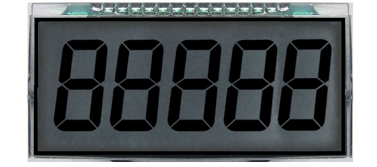
It looks like the OD-301 from Oriental Display but with 5 digits instead of 3 and 15 pins instead of 10. They also have an OD-6010 with 6 digits and some colons.
For 5 digits you have 35 segments. There can't be only 2 commons since 2 * 13 is less than 35. I think there are three commons since 3 * 12 = 36.
Try this sketch:
void setup()
{
  analogWrite(3, 127);  // 5V square wave on Pin 3
}

void loop() {}
Then use wires from Ground and Pin 3 to try pairs of pins to see which segment each pair lights (if any).
Here is an Application Note from Atmel/Microchip that says how to drive an LCD matrix from IO pins:
For a 5-digit 7-segment display, I'd expect a traditional multiplexed arrangement with one common for each digit and 7 segment pins connecting to all of the digits. (But perhaps there are additional limitations because of the signals being routed on glass.)
(Wow. I did some web-searching for examples of other segmented LCD displays, and it seems like nearly all of the datasheets REALLY SUCK (and rarely include pinout info.))
The 6-digit model has 16 pins, of which 4 are commons. I think they try to minimize the number of commons to allow for more frequent refreshes.
So you are going to use this with a proper LCD driver chip, aren't you?
Clearly you need to match the driver chip with the display. So you need the datasheet for the display, which should have come with the display - from where did you purchase it? The datasheet will also specify the correct voltages.
This is in itself, not an Arduino problem as you are not going to use an Arduino to drive it without the correct display driver chip. ![]()
Sir.I want to know how do you think 312 and 213 .
I just test what is common pin
Your other topic on the same subject deleted. Why did you start a new topic ?
Please do not duplicate your questions as doing so wastes the time and effort of the volunteers trying to help you as they are then answering the same thing in different places.
Repeated duplicate posting could result in a temporary or permanent ban from the forum.
Could you take a few moments to Learn How To Use The Forum
It will help you get the best out of the forum in the future.
Thank you.
I think NOT 2x13 because that can only address 26 of the 35 segments.
I think the 15 pins will be arranged as a 3x12 matrix.
Only possible answer. Three "common" pins, not one.
Certainly not anything related to Arduinox! ![]()
![]()
With 15 pins and 35 segments, 4x11, 5x10, 6x9, and 7x8 would also work but I think they try to minimize the number of commons.
Sir.I knew what on pin in lcd.Now I test to drive lcd with TM1721 IC and arduino Mega.But I have no code.Can you give me test code with TM1721IC and Arduino Mega?
Have you looked online for that? There are flow charts on pages 13-14 of the data sheet:
https://datasheet.lcsc.com/lcsc/1810281010_TM-Shenzhen-Titan-Micro-Elec-TM1721_C94297.pdf
This topic was automatically closed 180 days after the last reply. New replies are no longer allowed.