How to wire a 6 digit 7 segment display

Hi,

For one of my project i need to wire two 6 digit 7 segment displays to an arduino mega pro,
but i can't figure out how to hook them up to my arduino.
Could semoene help me please?

https://www.houkem.com.cn/mini-0-36-inch-6-digit-seven-segment-multidigit-digital-7-segment-led-display-amber.html thats the 7 segment display i use.

One of the images on the link you posted is a drawing with the 6dig7seg pins you need to connect... Looks like you need fourteen pins...

1 Like

This might be your lucky day, I found your project (almost) here: https://docs.arduino.cc/built-in-examples/display/RowColumnScanning/
Let us know how you do!

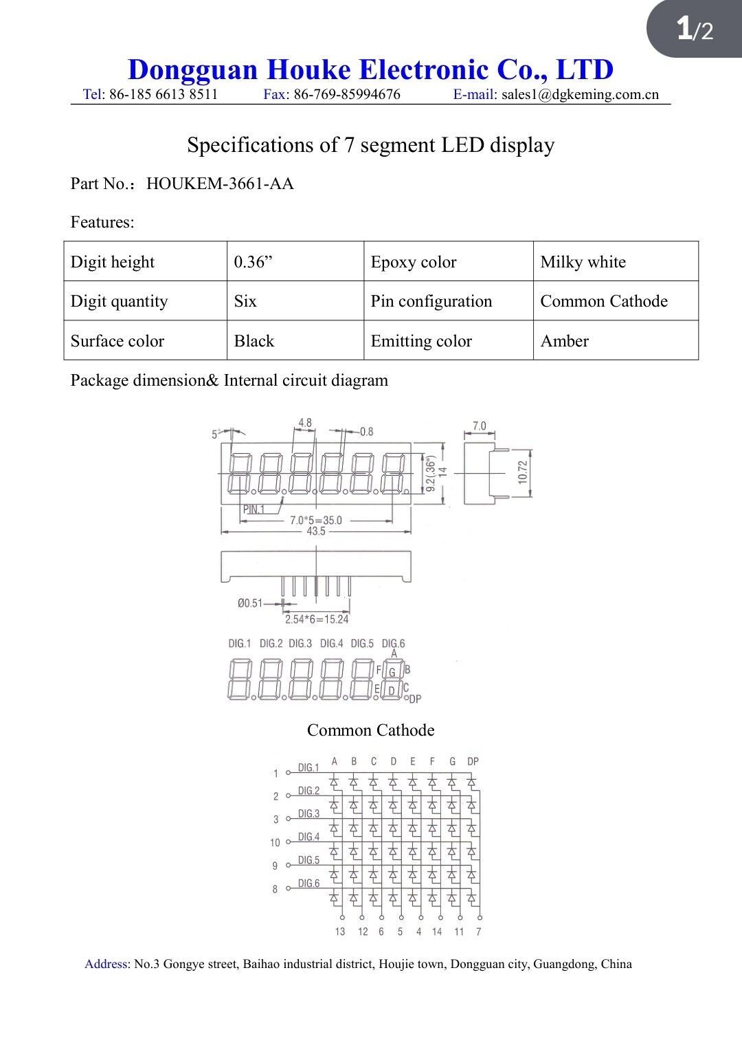
You don't seem to say whether you are using common cathode or common anode versions. If you are fortunate enough to be using the former, you would be well advised to use the MAX 7219 to drive it.

Arduino Playground - MAX72XXHardware

That's three pin's on Arduino. I know Mega has scads of pins, but why would you want to make life more difficult? If I recall correctly, 7219 will support eight digits
If common anode, there is likely to be some sort of equivalent. Common anything means not fourteen pins.

1 Like

That will work, but 2x 6digit displays will take pretty much all of the pins (8pins for the segments (inc DP), and 12 for the 12 digit cathodes.

Most often you see people throw additional chips at the problem.
MAX7219 8seg*8 digit driver via SPI
HT16K33 16seg*8 digit driver via I2C
TM1638 10seg*8 digit driver via SPI-like

(beware, such driver chips usually only work with common-cathode OR common-anode LEDs, although other chip variants from the same manufacturer may do the other. You have to be careful to get the right 'gender.')

Check this out, it only needs 4 pins plus power.

I can choose between common anode and cathode because it has a version for the two of them

The manufacturer gave me there documentation if that can serve to anyone


1. Try the following multipleded type 6-digit cc-type 7-segment diaply unit (Fig-1) sing SevSeg.h Librray.


Figure-1:

2. Uplod the following sketch (untested) to see 123456 on the display unit.

#include<SevSeg.h>
SevSeg sevSeg;           //create object sevSeg

int numberToShow = 123456;

void setup()
{
  byte segDPins[] = {8, 9, 10, 11, 12, 13, 6, 7};  //DPin8 = seg-a, …, DPin-7 = seg-p
  byte ccDPins[] = {A0, A1, A2, A3, A4, A5};          //DPin-A0 = cc0, DPin-A1 = cc1, ...
  sevSeg.begin(COMMON_CATHODE, 4, ccDPins, segDPins, false, false, false, true);
  sevSeg.setNumber(numberToShow, 0, LOW);
}

void loop()
{
  sevSeg.refreshDisplay();
}

That wiring diagram does not appear to match the display data sheet in post #8.

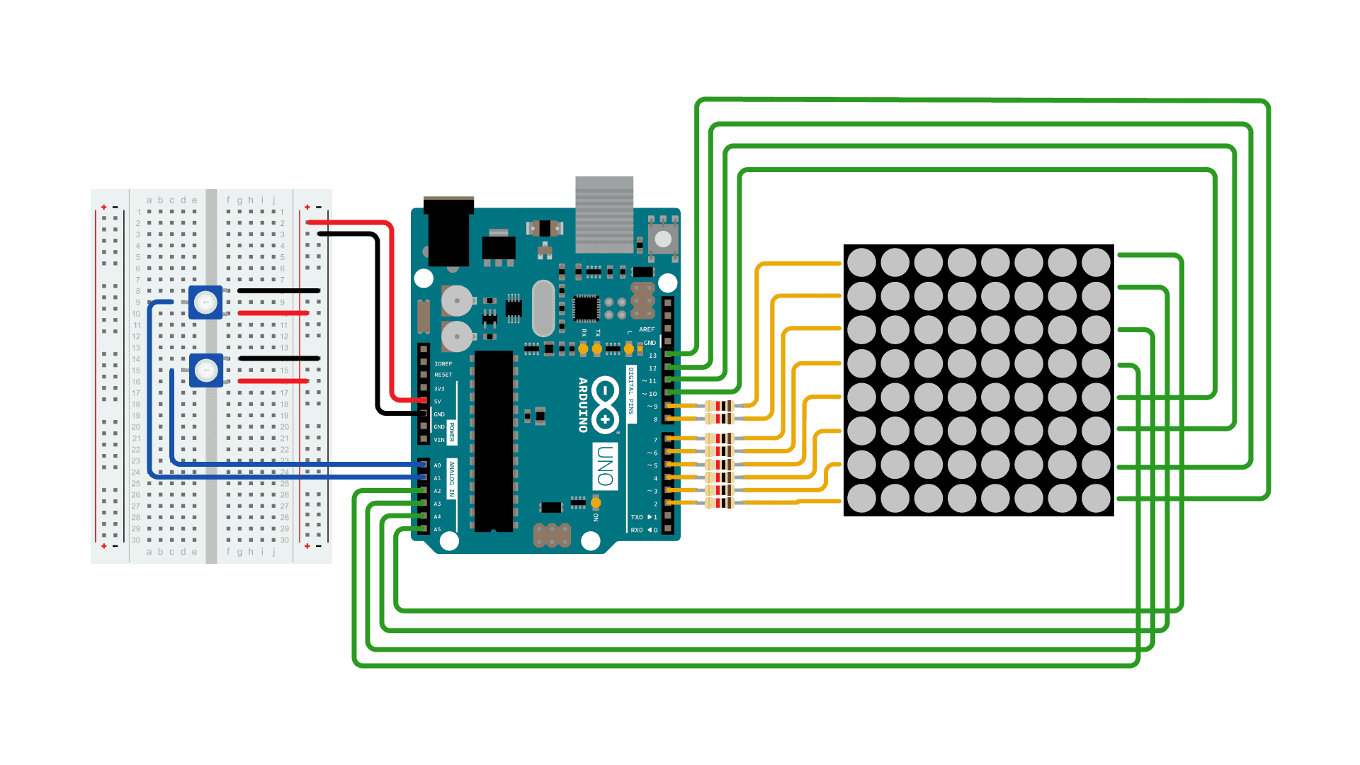
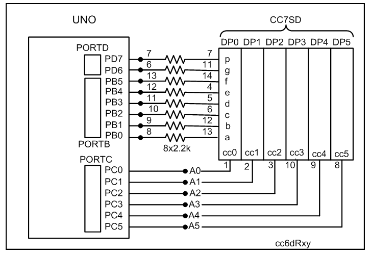
1. The OP may use a DVM (or follow diagram of post #10 @6v6gt, Fig-1 repeated ) to find the segment pins and cc-pins of the display devices (assuming the display devices are of cc-type) and then easily connect his display unit with UNO (Fig-1) following the guidance of Fig-2 of post #9.


Figure-1:


Figure-1:

2. Uplod the following sketch (untested) to see 123456 on the display unit.

#include<SevSeg.h>
SevSeg sevSeg;           //create object sevSeg

int numberToShow = 123456;

void setup()
{
  byte segDPins[] = {8, 9, 10, 11, 12, 13, 6, 7};  //DPin8 = seg-a, …, DPin-7 = seg-p
  byte ccDPins[] = {A0, A1, A2, A3, A4, A5};          //DPin-A0 = cc0, DPin-A1 = cc1, ...
  sevSeg.begin(COMMON_CATHODE, 4, ccDPins, segDPins, false, false, false, true);
  sevSeg.setNumber(numberToShow, 0, LOW);
}

void loop()
{
  sevSeg.refreshDisplay();
}

OK. That diagram and code appears to better match the data sheet for the display although the sevSeg constructor appears to be configured for a 4 digit display.

It seems he has a Mega, not a Uno (see post #1), which is a good thing because, for a Uno, a direct driven 6 digit 7 segment display leaves only a few pins for the actual application.

I have provided an untested sksetch which the OP may adjust if deos not work.

The standard Arduino is the ARDUINO UNO and the standard way of writing name is "ARDUINO UNO" and NOT "arduino uno" and "ARDUINO MEGA" and NOT "arduino mega".

Hi,

I just wanna confirm i didnt made any errors on my circuit, i now it is very dense and sometime hard to differantiate the wires.
Schematic_Radio-Communication-A320_2025-02-06.pdf (191,0 Ko)

Is this question in relation to your other topic ?

kind of

Your two or more topics on the same or similar subject have been merged.

Please do not duplicate your questions as doing so wastes the time and effort of the volunteers trying to help you as they are then answering the same thing in different places.

Please create one topic only for your question and choose the forum category carefully. If you have multiple questions about the same project then please ask your questions in the one topic as the answers to one question provide useful context for the others, and also you won’t have to keep explaining your project repeatedly.

Repeated duplicate posting could result in a temporary or permanent ban from the forum.

Could you take a few moments to Learn How To Use The Forum

It will help you get the best out of the forum in the future.

Thank you.

This topic was automatically closed 180 days after the last reply. New replies are no longer allowed.