OK. I'm warning you, what you are about to read is a deep dive down a technical rabbit hole! You've been warned!
Here's what I have:
I have a racing simulator (iRacing), and I want to build a fairly unconventional motion simulator. I understand motion sims have been done a billion times, but this one is significantly different. Hear me out.
Long story short - I don't have room for a race sim in my house. (Wife says NO). So, I bought a non running car (2005 Ford Escape). I took out the passenger seat, and mounted a desktop gaming PC to the passenger floor. Power and internet comes in via buried cable from the house. I gutted the steering column of the escape, and installed a racing sim wheel where the factory steering wheel was. I then mounted a monitor just behind the windshield(inside). I then connected the gas pedal to the PC. The brake system I modified, and installed a pressure sensor, connecting that sensor to the PC. Now I have working factory brake / gas pedals, and a rough placement of steering inputs and a rough draft of video display (those are being changed, but irrelevant here).
I live in south Florida, so the Escape gets hot. I removed part of the rear seat and gas tank, cut a hole in the floor, and mounted a window air conditioner in said hole. With the help of mirrored window tint to keep out sunlight / heat, as well as some windshield mounted solar panels to charge the 12V system (barely gets used - but it helps with preventing thermal heat entry), the Escape now stays nice and cool.
Sound is taken from the PC, amplified, and run into the factory car speakers.
This all works. I can go out in my Escape and play on my race sim in comfort, and it works. I'm moving the seat to the middle of the escape so I can run 3 monitors, but that's another topic.
SIDE note (but will become relevant soon): Again, I live in south Florida. Hurricanes, storms, and power outages are a way of life. Several years ago, I purchased a trailerable light tower for emergency back up power. This is wired into the house, and provides us emergency back up power when the power goes down. (This is NOT, nor WILL NOT be used to power the race sim electronics or computers ever). DOWNFALL to the light tower - it sits in an unsightly metal box trailer. Compact, but ugly none the less.
Here's where my diabolical plan begins. I have a Ford Escape with a bad engine. The escape will NEVER move under its own power again - don't need it to.
The light tower never needs to move again. Soooo.....
I want to remove the engine / transmission from the dead Ford Escape. Throw it away; gone forever; no longer needed. Next, I want to remove the diesel engine and generator from the light tower, discard the trailer and install it where the Escape engine used to be - now I would only have 1 "vehicle" in my back yard, with a diesel generator conveniently hidden under the hood of my immobile "stock appearing to nosey neighbors" Ford Escape.
I'm 110% good up till this point. Now I have a race sim escape that conveniently houses my emergency generator. Cool.
Here's where it gets wild. What if I hooked up a hydraulic pump to the generator engine (I have this part figured out). Then, I could remove the struts / springs / shocks from each wheel, and replace them with hydraulic cylinders. On the rear wheels, I could fabricate a tie bar connected to the rear wheels that would move the bottoms of the rear tires left or right (picture pushing the escape side to side). I have 100% of the mechanics figured out on this. (I'm comfortable with the fabrication and hydraulics of this).
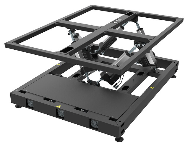
Ultimately, I want to create a hydraulically powered motion sim out of my Ford Escape. Instead of moving a seat, I want to move the entire vehicle that I'm sitting in. Over simplified, when I step on the gas, the 2 front hydraulic cylinders will extend raising the front of the escape; the 2 rear cylinders will contract, thus lowering the escape, giving the feel of accelerating. Braking will do the opposite. Turning left will contract the two right side suspension cylinders, and extend the left. Right turns, visa versa. If I accelerate too hard out of a turn and get loose, the 5th cylinder (rear wheel tie bar) will extend, pushing the bottoms of the tires left (making it feel like the rear end is swinging right - simulating a rear end sliding motion).
I have played with basic arduino in the past. I've bought the kits, made LEDs flash, even built proximity sensors for to tell the distance of another vehicle / object. BUT, my arduino experience is limited. I do have experience with motion control / sensors / actuators in an industrial setting. But Arduino I'm not so well versed in.
Now here's where it gets fuzzy for me. I know guys are using arduino to build motion sims in their homes, controlling rotary motors / linear actuators. So I would assume since the other projects are simply utilizing electric signals to control motors / actuators, i SHOULD be able to control electro hydraulic actuators to achieve my goal, correct? How does that interface with the PC? How insane am I going to have to go (learning wise) to write a code for something like that?
