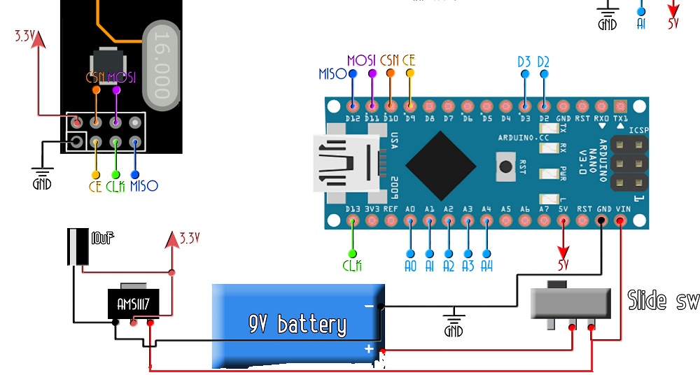
Hello all, I have recently been following an online tutorial on how to build an Arduino drone, the flight controller is done. i am building the transmitter (controller) I will include the schematic along with pictures now

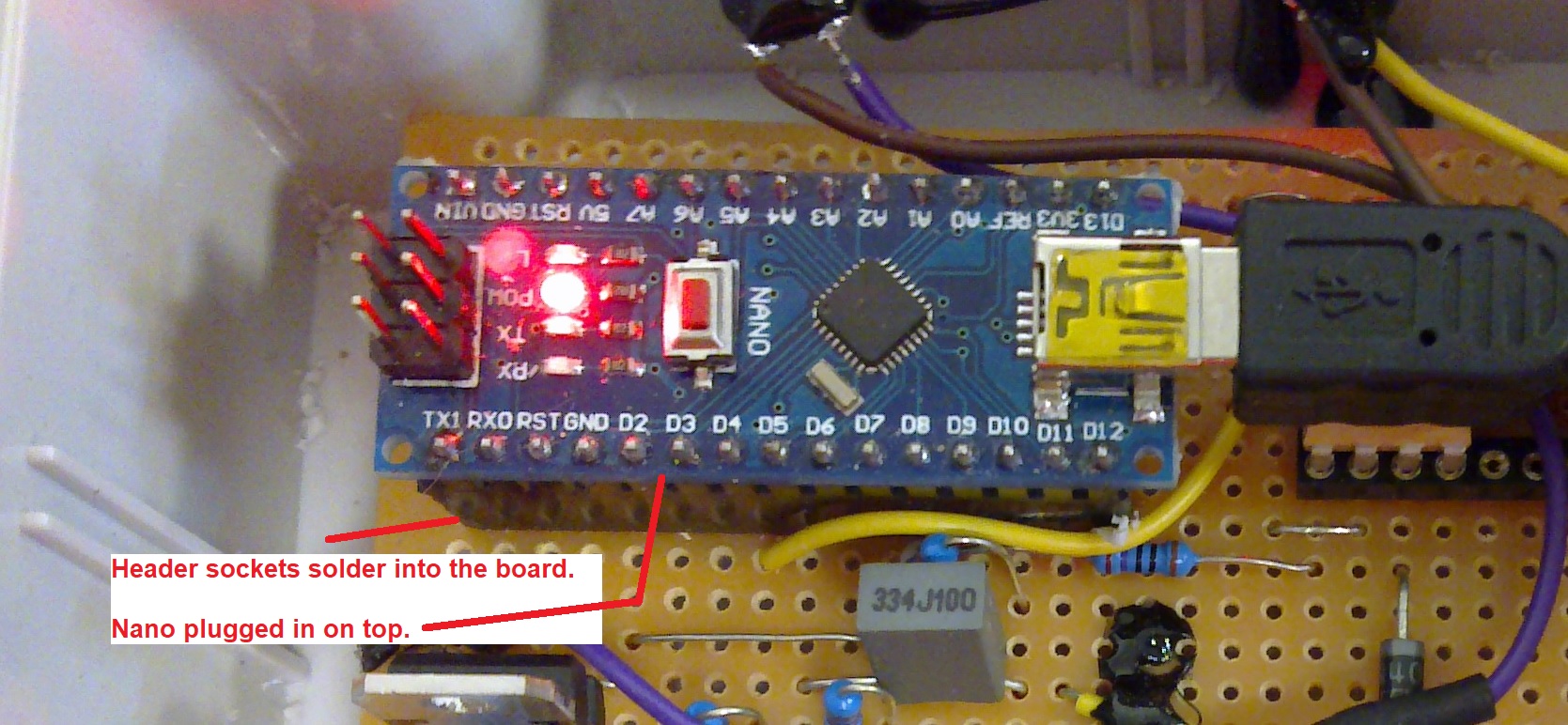
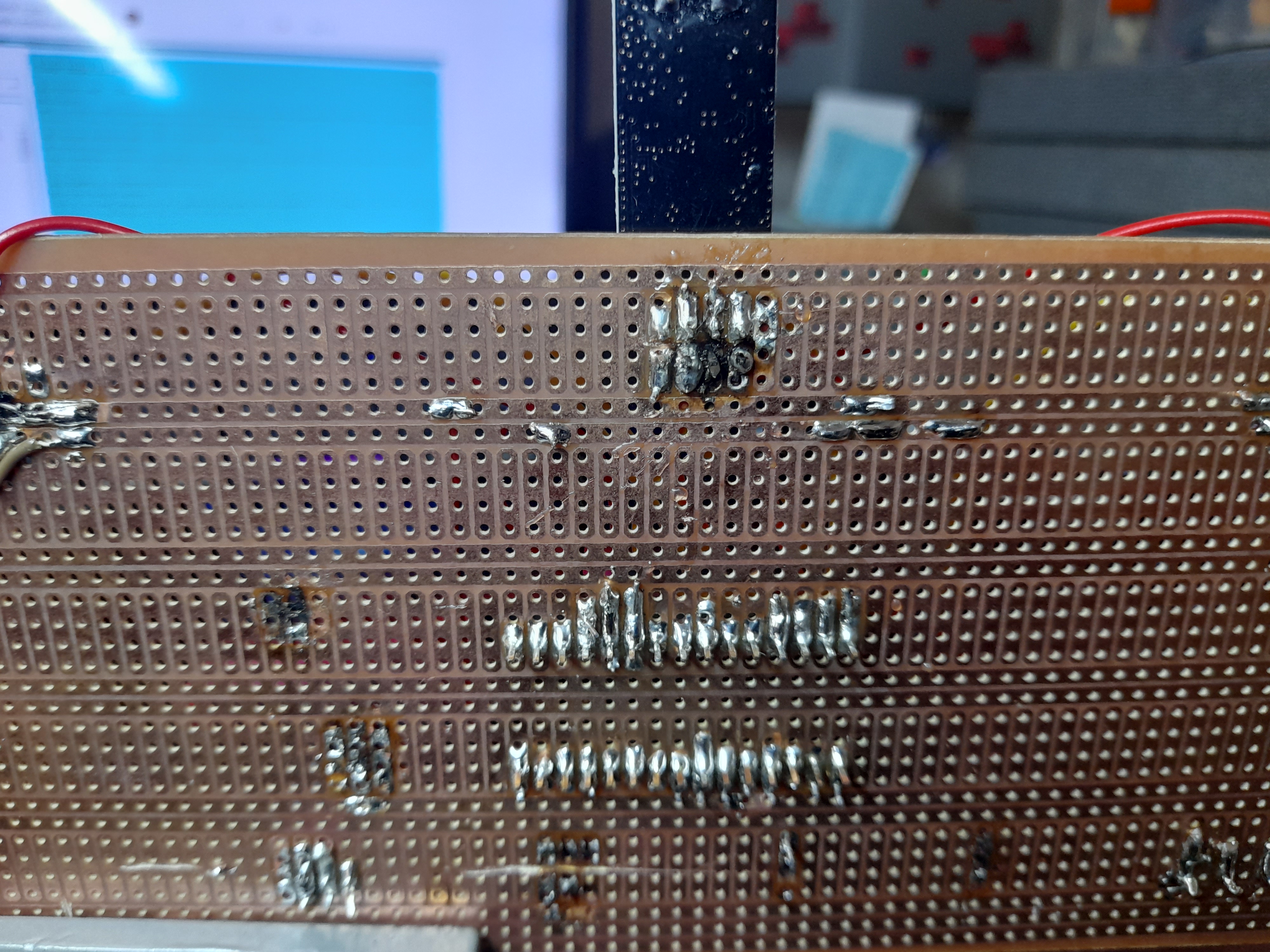
The next image is to showcase my poor soldering skills maybe you will look at this and believe that this is the problem, I just want to mention that I am using Draper solder wire, with flux inside and it seems to be very good solder wire I just need practise.
Now returning to my query I have came across a strange problem, upon plugging the 9 volt battery in the red LED on the arduino nano came on, however after switching the switch on the LED I switched the main power switch on and the LED became brighter,(want to quickly mention even with the switch in the off position I was getting the same voltage readings, I desoldering and removed the switch, tested continuity on the switch and it seems okay as it beeps with the switch on, and doesn't when its off)
I measured some points of the circuit with my multimeter, I am suppose to read ~3.3 volts to the NRF24 radio controller and 5volts top the arduino.
However my reading were 1.7v between 5v and GND, 2.7v between Vin and NRF24 gnd, and 3.6v between 5v and NRF24 gnd. very strange how I am getting some voltage but not nearly enough, and to add to this issue, I noticed the LED on the nano quickly dimming before my eyes, until it was completely off, and the voltage reading for each were slightly lower this time, here are my results after 5 and 15 mins(I will will include the before-mentioned values next to these so you guys have an easier time comparing them) :
(I rounded all these to one decimal place)
1.7v between 5v and GND, after 5mins = 1.4v after 15mins = 1v
2.7v between Vin and NRF24 gnd, after 5mins = 2.4v after 15mins = 2v
3.6v between 5v and NRF24 gnd, after 5mins = 1.5v after 15mins = 1v
I noticed after doing this that the point in between Vin and NRF24 gnd were maintaining a similar voltage reading, whilst the points between 5v and NRF24 gnd dropped drastically.
I don't know whether it is something to do with the 10mF capacitor or AMS1117 5.0 DN911 voltage regulator, or whether my awful soldering skills have caused issue such as short circuits, its very difficult to tell as a beginner. This is the first thing I have ever really soldered and its been tough to say the least, any help would be greatly appreciated thank you very much for reading this far!