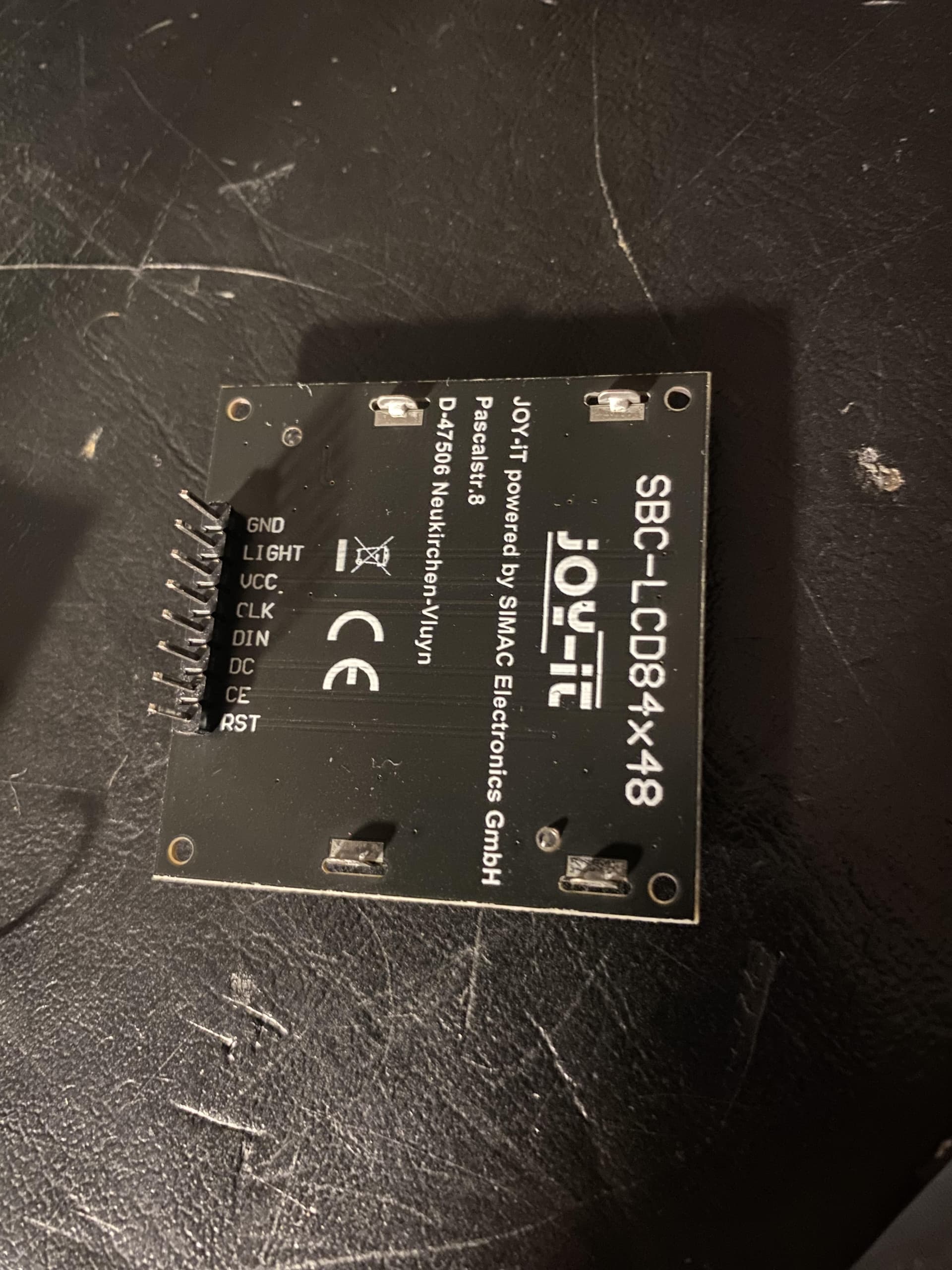


#include <LCD5110_Graph.h>
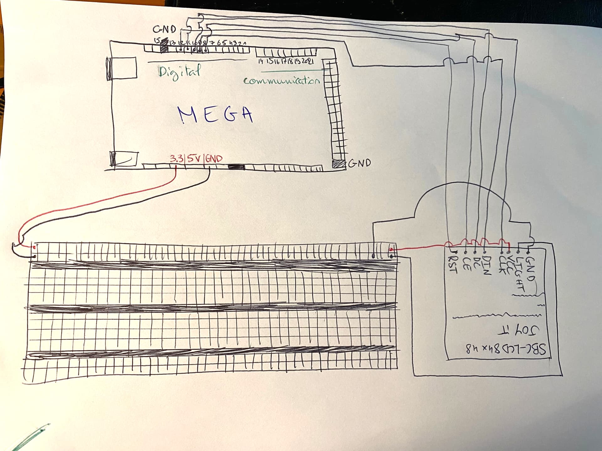
LCD5110 myGLCD(8,9,10,12,11);
extern uint8_t SmallFont[];
// Mux control pins
int s0 = 2;
int s1 = 3;
int s2 = 4;
int s3 = 5;
// Mux in "SIG" pin
int SIG_pin = A0;
void setup() {
myGLCD.InitLCD();
myGLCD.setFont(SmallFont);
randomSeed(analogRead(7));
pinMode(s0, OUTPUT);
pinMode(s1, OUTPUT);
pinMode(s2, OUTPUT);
pinMode(s3, OUTPUT);
digitalWrite(s0, LOW);
digitalWrite(s1, LOW);
digitalWrite(s2, LOW);
digitalWrite(s3, LOW);
Serial.begin(9600);
myGLCD.clrScr();
myGLCD.print(const_cast<char*>("Ready?"), CENTER, 20);
myGLCD.update();
}
int gameRounds = 0;
int totalScore = 0;
void loop() {
bool sensorTriggered = false;
while (!sensorTriggered) {
for (int i = 0; i < 4; i++) {
if (readMux(i) > 0.35) {
sensorTriggered = true;
break;
}
}
}
if (gameRounds < 10) {
int score = startGame();
totalScore += score;
gameRounds++;
} else {
displayEndMessage();
delay(10000); // Attendre 10 secondes avant de redémarrer les rounds
gameRounds = 0;
totalScore = 0;
}
delay(1000);
}
void displayEndMessage() {
myGLCD.clrScr();
myGLCD.print(const_cast<char*>("Felicitation!"), CENTER, 0);
myGLCD.print(const_cast<char*>("Les 10 rounds"), CENTER, 10);
myGLCD.print(const_cast<char*>("sont termines."), CENTER, 20);
myGLCD.print(const_cast<char*>("Score total:"), CENTER, 30);
myGLCD.printNumI(totalScore, CENTER, 40);
myGLCD.update();
}
int startGame() {
int targetChannel = random(4);
myGLCD.clrScr();
myGLCD.print(const_cast<char*>("Eclairez"), CENTER, 0);
myGLCD.print(const_cast<char*>("capteur"), CENTER, 10);
myGLCD.printNumI(targetChannel, CENTER, 20);
myGLCD.update();
unsigned long startTime = millis();
int remainingTime = 30;
bool answeredCorrectly = false;
bool wrongSensorTriggered = false;
int score = 0;
while (remainingTime > 0 && !answeredCorrectly && !wrongSensorTriggered) {
unsigned long currentTime = millis();
if (currentTime - startTime >= 1000) {
startTime = currentTime;
remainingTime--;
// Afficher le temps restant
myGLCD.clrRect(0, 40, 83, 47); // Effacer la zone du timer
myGLCD.print(const_cast<char*>("Temps: "), LEFT, 40);
myGLCD.printNumI(remainingTime, 40, 40);
myGLCD.update();
}
float luxValue = readMux(targetChannel);
if (luxValue > 0.35) {
answeredCorrectly = true;
score = remainingTime * 100 / 30;
}
// Vérifier si un mauvais capteur a été éclairé
for (int i = 0; i < 4; i++) {
if (i != targetChannel) {
if (readMux(i) > 0.35) {
wrongSensorTriggered = true;
break;
}
}
}
}
myGLCD.clrScr();
if (answeredCorrectly) {
myGLCD.print(const_cast<char*>("Bien joue !"), CENTER, 20);
myGLCD.print(const_cast<char*>("Score: "), LEFT, 30);
myGLCD.printNumI(score, 40, 30);
} else if (wrongSensorTriggered) {
myGLCD.print(const_cast<char*>("Reessaie"), CENTER, 20);
} else {
myGLCD.print(const_cast<char*>("Temps ecoule"), CENTER, 20);
}
myGLCD.update();
delay(3000);
return score;
}
float readMux(int channel) {
int controlPin[] = {s0, s1, s2, s3};
int muxChannel[16][4] = {
{0, 0, 0, 0},
{1, 0, 0, 0},
{0, 1, 0, 0},
{1, 1, 0, 0},
{0, 0, 1, 0},
{1, 0, 1, 0},
{0, 1, 1, 0},
{1, 1, 1, 0},
{0, 0, 0, 1},
{1, 0, 0, 1},
{0, 1, 0, 1},
{1, 1, 0, 1},
{0, 0, 1, 1},
{1, 0, 1, 1},
{0, 1, 1, 1},
{1, 1, 1, 1}
};
for (int i = 0; i < 4; i++) {
digitalWrite(controlPin[i], muxChannel[channel][i]);
}
int val = analogRead(SIG_pin);
float voltage = (val * 5.0) / 1024.0;
float resistance = (5.0 - voltage) * 10000.0 / voltage;
float lux = 500.0 / resistance;
return lux;
}
moderator edit: code tags