This post is not a question but rather a sharing of my failure story derived from following thread:
@Grumpy_Mike gave me the following comment about the oscilloscope image of the I2C SCL that I posted in #post 43.
I think this kind of knowledge is very useful for people like me who have little knowledge of hardware to identify the cause when a problem occurs. So I report my additional experiments and results.
In this post, I will mainly report on the following two points.
- The SCL waveform and frequency with and without an I2C pull-up resistors.
- Limitation and actual measurements for the I2C clock of ESP32S3.
Overview
In the block diagram below, I observed the SCL of the I2C in the left half with and without two pull-up resistors for SDL and SCL.

And here are the specs related to I2C.
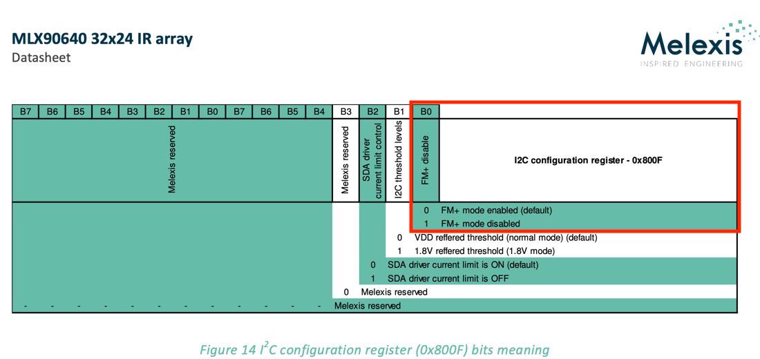
I2C slave: MLX90640
The default I2C bus speed of MLX90640 is Fast-mode plus, i.e. 1Mbsp.
I2C master: ESP32S3
The ESP32 S3 datasheet states that the I2C bus speed is up to 800Kbps.
And the actual code is limited to 1Mbps by i2cSetClock(), so we cannot set it higher than 1Mbps.
For reference, this is the code I used for testing
#include <Arduino.h>
#include <Wire.h>
#include <Adafruit_MLX90640.h>

Adafruit_MLX90640 mlx;

// 0_5_HZ, 1_HZ, 2_HZ, 4_HZ, 8_HZ, 16_HZ, 32_HZ or 64_HZ
#define REFRESH_RATE  MLX90640_32_HZ

// 400000, 800000, 1000000, 1600000
#define I2C_BUS_CLOCK 1000000

// The size of thermal image
#define MLX90640_COLS 32
#define MLX90640_ROWS 24

float src[MLX90640_ROWS * MLX90640_COLS];

void setup() {
  Serial.begin(115200);

  if (! mlx.begin(MLX90640_I2CADDR_DEFAULT, &Wire)) {
    Serial.println("MLX90640 not found!");
  } else {
    Serial.println("MLX90640 found");
  }

  // MLX90640
  mlx.setMode(MLX90640_CHESS);
  mlx.setResolution(MLX90640_ADC_18BIT);  // 16BIT, 17BIT, 18BIT or 19BIT
  mlx.setRefreshRate(REFRESH_RATE);

  // I2C bus clock for MLX90640
  // Note: ESP32S3 supports up to 800 KHz
  Wire.setClock(I2C_BUS_CLOCK); // 400 KHz (Sm) or 1 MHz (Fm+)
  Serial.println(Wire.getClock()); // 1000000
}

void loop() {
  if (mlx.getFrame(src) != 0) {
    Serial.println("Failed");
    delay(1000); // false = no new wasframe captured
  }
}
Results
I set the I2C bus speed to 1Mbps on the master side. Here are the results:
-
No pull-up registers
-
2K registers
-
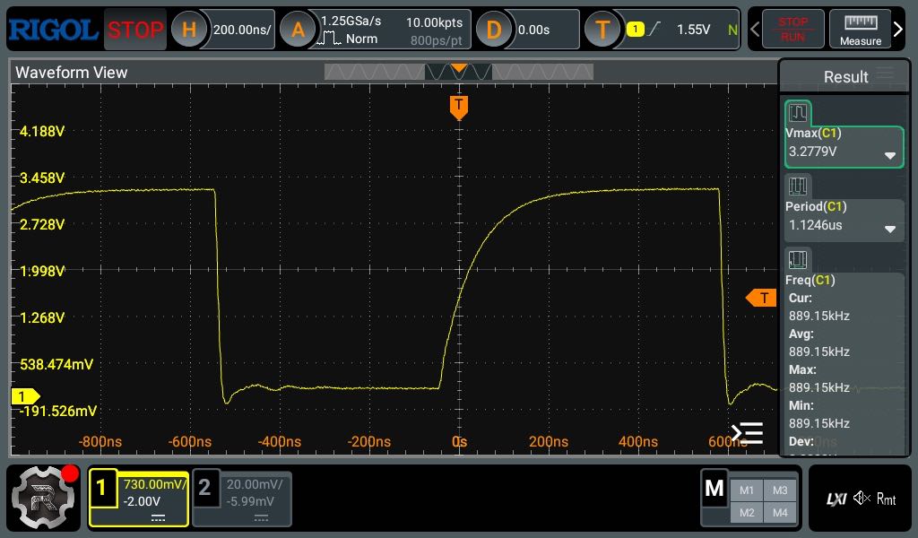
1K registers

For 1KΩ, I referenced the following recommended circuit from the latest data sheet. (As an aside, when I looked at this circuit diagram, I assumed that the MLX90640 breakout board had a pull-up resistor built in, which was my mistake.)

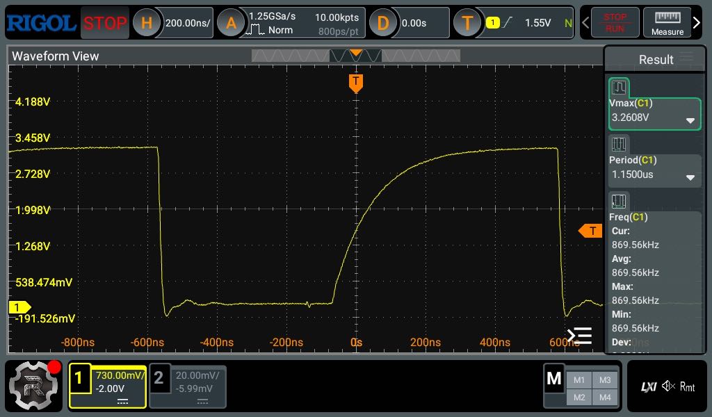
The waveform when I specified 800KHz with a 1KΩ pull-up resistors was as follows. Observed frequency is below 800KHz.
- 1K registers with 800KHz

What I can see from these results is that while the MLX90640 on the slave side has plenty of power to spare, the I2C clock is limited by the ESP32S3 on the master side.
At first I thought something was wrong because the waveform was so dull, but I left it alone without looking deeper.
First I need to develop my experience-based intuition to recognize that something is wrong. Secondly, I would like to develop the ability to dig deeper to find the cause.
I hope this helps someone.
P.S.: There are so many categories, I don't know which one is appropriate!