just today i got a TFT Display
this one to be exact: AMAZON
it's a very standard part.
first thing i did was hook it up, as seen on the amazon page it has a built-in 8 bit Bus Transceiver (SN74LVC245A) that functions as a level shifter so i should be able to easily run this at 5V without issue.
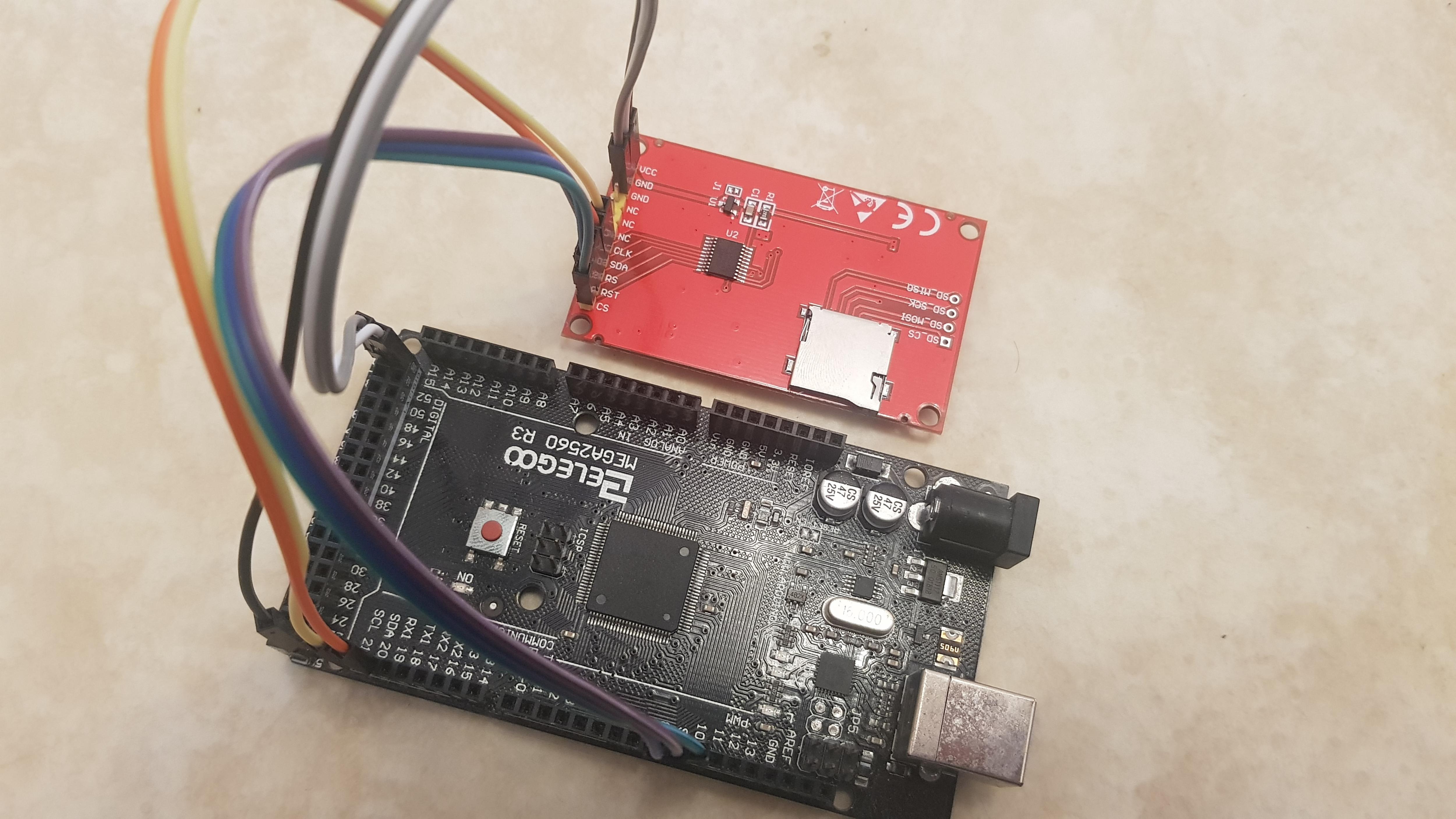
here is how i hooked it up to my Arduino Mega 2560:
Display ---- Arduino

CS --------- Pin 10
RST -------- Pin 8
RS(DC) ----- Pin 9
SDA -------- Pin 20
CLK(SCL) --- Pin 21
NC
NC
NC
GND -------- GND
GND -------- GND
VCC -------- +5V
i tried the example sketch "I2C_scanner" to see what ID it would be but it was unable to find it.
i also tried a TFT example sketch but as expected the display didn't do anything except stay completely white.
i've checked my connections multiple times and even used another Arduino, i also tested the same Arduinos and program with my tiny I2C OLED display and it was instantly recognized.
here are some pics on how it looks in RL (the wire lenghts shouldn't matter as my tiny OLED Display also works with the same wires):
what also adds to the confusion is that in the amazon page the display is shown connected to the opposite side to where the I2C pins are on the Mega, and it's running...
so either they bit-banged the I2C Interface, or it's shopped for some reason.
overall i hope i just missed something and that the display is not bricked.
It is not I2C.
It is SPI with a bidirectional data pin SDA. But the external electronics destroy the bidirectional ability.
Just accept it as a write-only display. Most ST7735 libraries never use the read features anyway.
David.
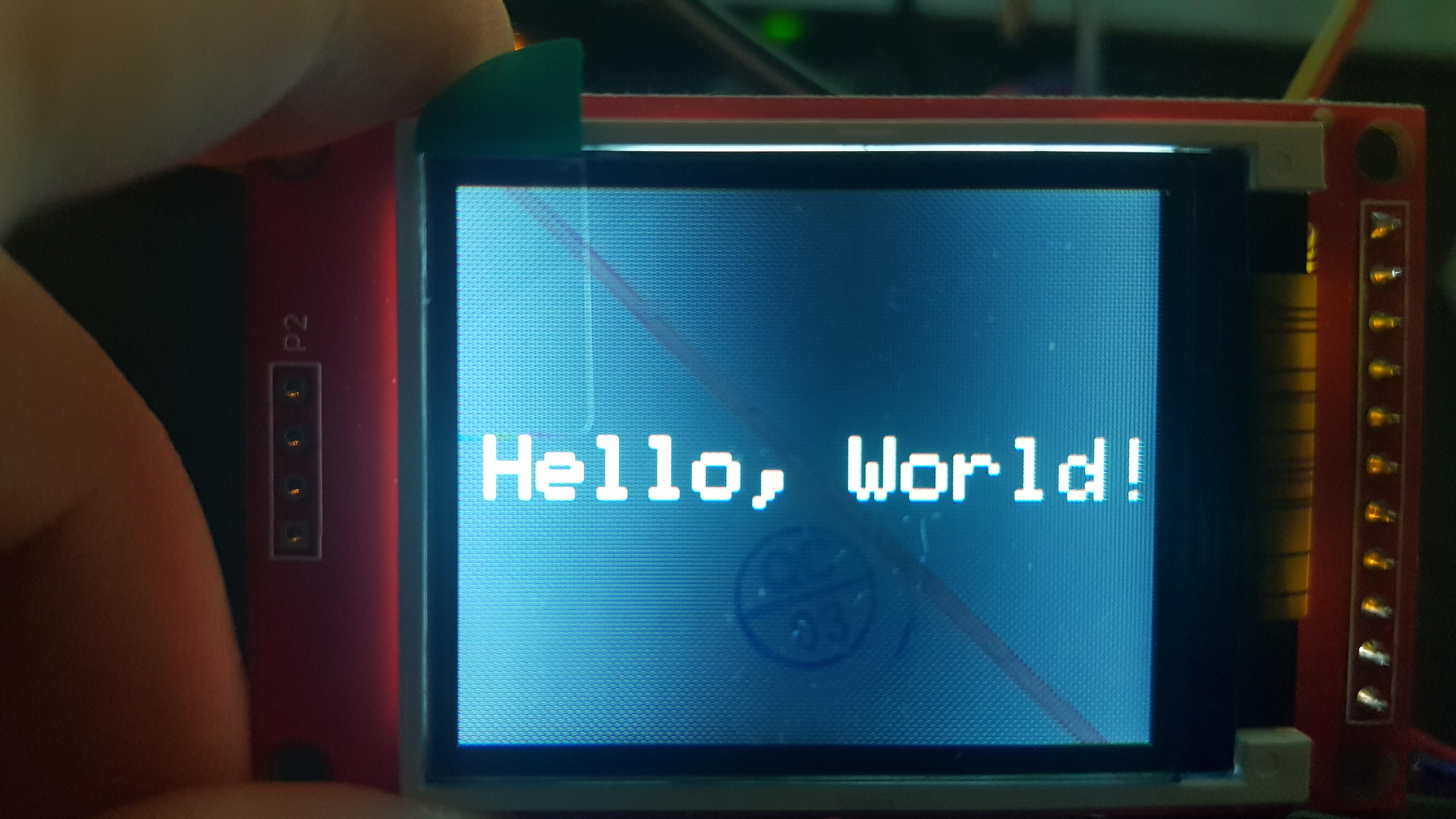
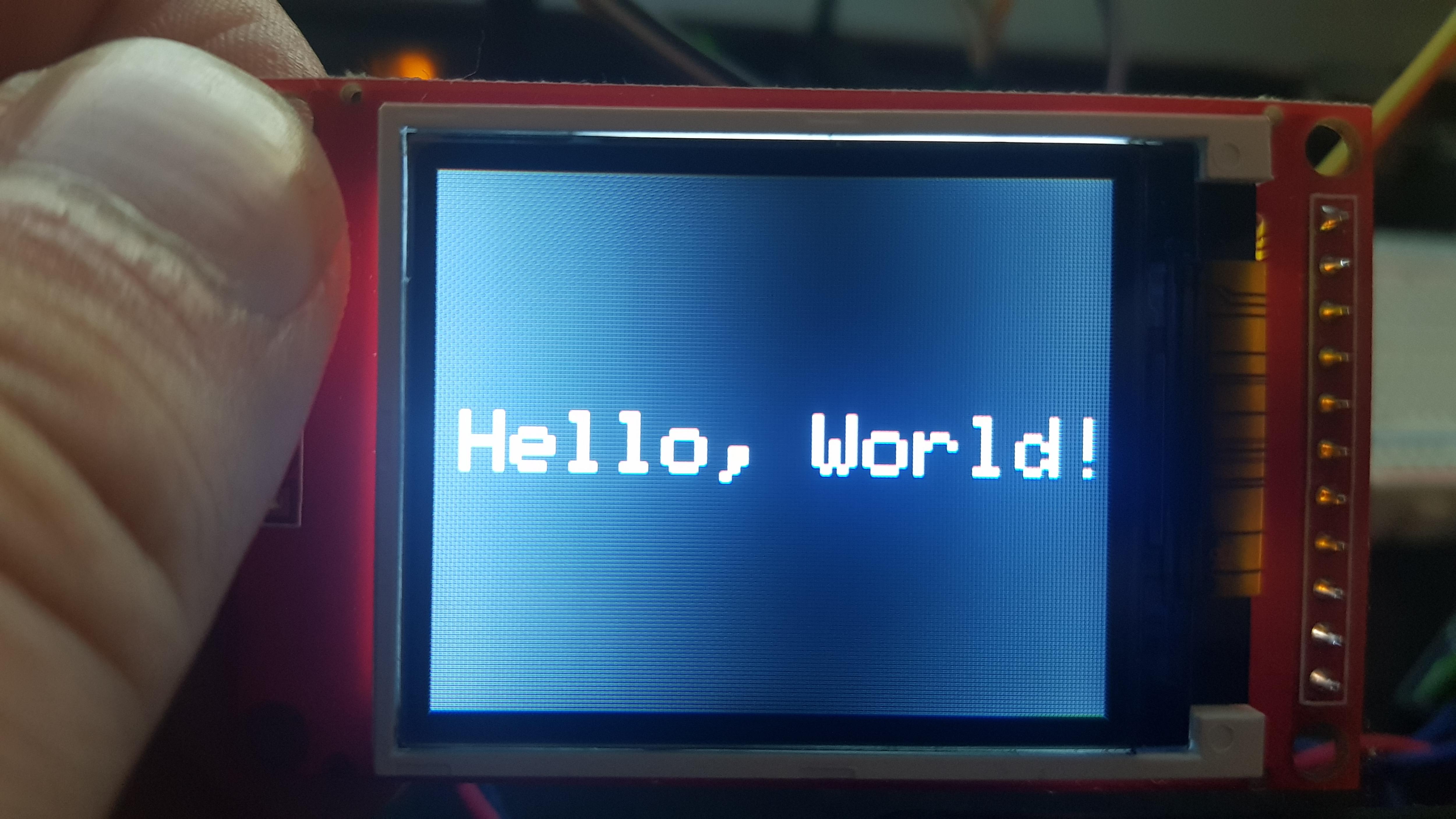
well frick me it works now.
i reconnected those 2 pins as follows:
SDA -------- Pin 51 (MOSI)
CLK -------- Pin 52 (SCLK)
though to be honest if there are 2 pins and one of them is called SDA and the other one is a CLK i instantly think of I2C...
well thanks for helping me fix this.
sadly the display doesn't have a brightness control pin, because it creates this weird pattern depending on how you look at it and it's strange on the eyes after a while...
Unpeel the green tab that destroys the picture quality (and brightness).
Most of these displays are "too bright". I suspect that R1 is the backlight series resistor.
SDA commonly means "Serial Data" normally bidirectional.
SDI means Serial Data In (MOSI)
SDO means Serial Clock
unpeeling the screen protector does slightly improve the quality but the main issue still persists.
(that being the brightness gradient that goes horizontally across the screen)
i only want the protector on there because... screen protection.
i can try to desolder R1 and replace it with a poti intially set to the same value so i can try and see if it is actually the brightness control.
thanks for the idea!
EDIT: looking at R1 it's a 2 Ohm Resistor (2R0)... so the backlight is set to basically 100% if it's that one?
I would not reduce 2R0. The backlight is already too bright. The LED is showing through the "BLACK" background.
I would try different tft.intR() arguments. To find the best "black" colour.
David.
why reduce R1? my idea was to use a poti to increase the value of it...
because i thought: higher resistance = less current = darker backlight
and lastly i cannot find anything that actually explains "initR" online... i only saw a few posts saying it was used to correct colors?
and i don't really think it's about colors, it's likely more about the poor viewing angles of TFT displays and the backlight being way too bright.
I would try series resistors from 3R3 to 22R.
Yes, most cheap TFTs have a very narrow viewing angle. Live with it.
Look in the Adafruit_ST7735.h header file. There are a choice of "typical" initialisation sequences. Just try them all. Choose the "best".
Note that the ST7735S comes with 4 on-chip GAMMA curves.
Choose the best one.
David.
david_prentice:
I would try series resistors from 3R3 to 22R.
but why soldering and desoldering different resistors on it when i can just solder on a potentiometer once and set the brightness manually with a screwdriver?
i have some that have a range of 0-100 Ohm.
also why do the values have to be so small anyways?
david_prentice:
Yes, most cheap TFTs have a very narrow viewing angle. Live with it.
yea sadly i think i just have to. kinda a shame.
david_prentice:
Look in the Adafruit_ST7735.h header file. There are a choice of "typical" initialisation sequences. Just try them all. Choose the "best".
Note that the ST7735S comes with 4 on-chip GAMMA curves.
Choose the best one.
thanks, I'll have to look through that once i fix the backlight brightness thing
I would do initR() and GAMMA first. Then adjust backlight.
Some maths:
Typical white LED backlight has Vf = 3.0V
AMS1117-3.3 regulator produces 3.3V
(3.3V - 3.0V ) / 2R0 = 150mA
(3.3V - 3.0V ) / 4R7 = 64mA
(3.3V - 3.0V ) / 10R = 30mA
(3.3V - 3.0V ) / 12R = 25mA
(3.3V - 3.0V ) / 15R = 20mA
(3.3V - 3.0V ) / 22R = 14mA
(3.3V - 3.0V ) / 47R = 6mA
It is probably handy to use a 47R variable resistor. But I would just solder a 15R resistor and be done with it.
David.