Dear All,
i digged and did not find the answer.
How can i use the INA3221 as a voltmeter, measuring the voltage generated by a small motor?
Thx in advance for any hint.
Dear All,
i digged and did not find the answer.
How can i use the INA3221 as a voltmeter, measuring the voltage generated by a small motor?
Thx in advance for any hint.
Motors don't generally generate voltage, unless you are using them as a generator.
Otherwise, buy a INA3221 module, wire it up, then communicate with i2c. There is a library
@pw44
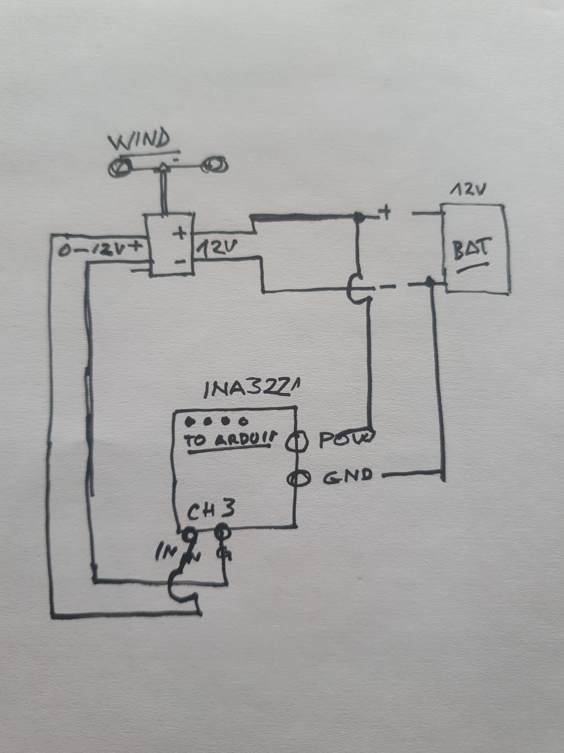
Connect the INA3221 ground (GND) to the motor negative lead.
Connect any of the IN- pins to motor positive lead
Connect a diode between the INA3221 IN- and ground. Connect the cathode to the IN- pin
IN- must be less than 26V and must be a POSITIVE voltage. Make sure you are spinning the motor in the correct direction to generate a POSITIVE voltage.
Do NOT connect anything to the IN+
Make sure you have the module with the 3 separate connections IN+1, IN-1, IN+2, IN-2, IN+3, IN-3.
Thx.
idea is: motor as generator from 0V to 5V being read by INA3221 CH1 and having reult displayed by Arduino (any) via i2c, so, INA3221 VCC (3V3), GND, SDA and SCL to Arduino board and motor output + to CH1 and GND of INA3221 - motor will be turned by wind. Is it feaseable?
Thx
If you do everything as I explained and use the correct INA3221 module, yes it is possible
However, the resolution of the INA3221 is 8mV, is that good enough?
No it is not. There may be a much simpler way to do it by just using the Arduino ADC.
Are you trying to measure the output of a 12V anemometer?
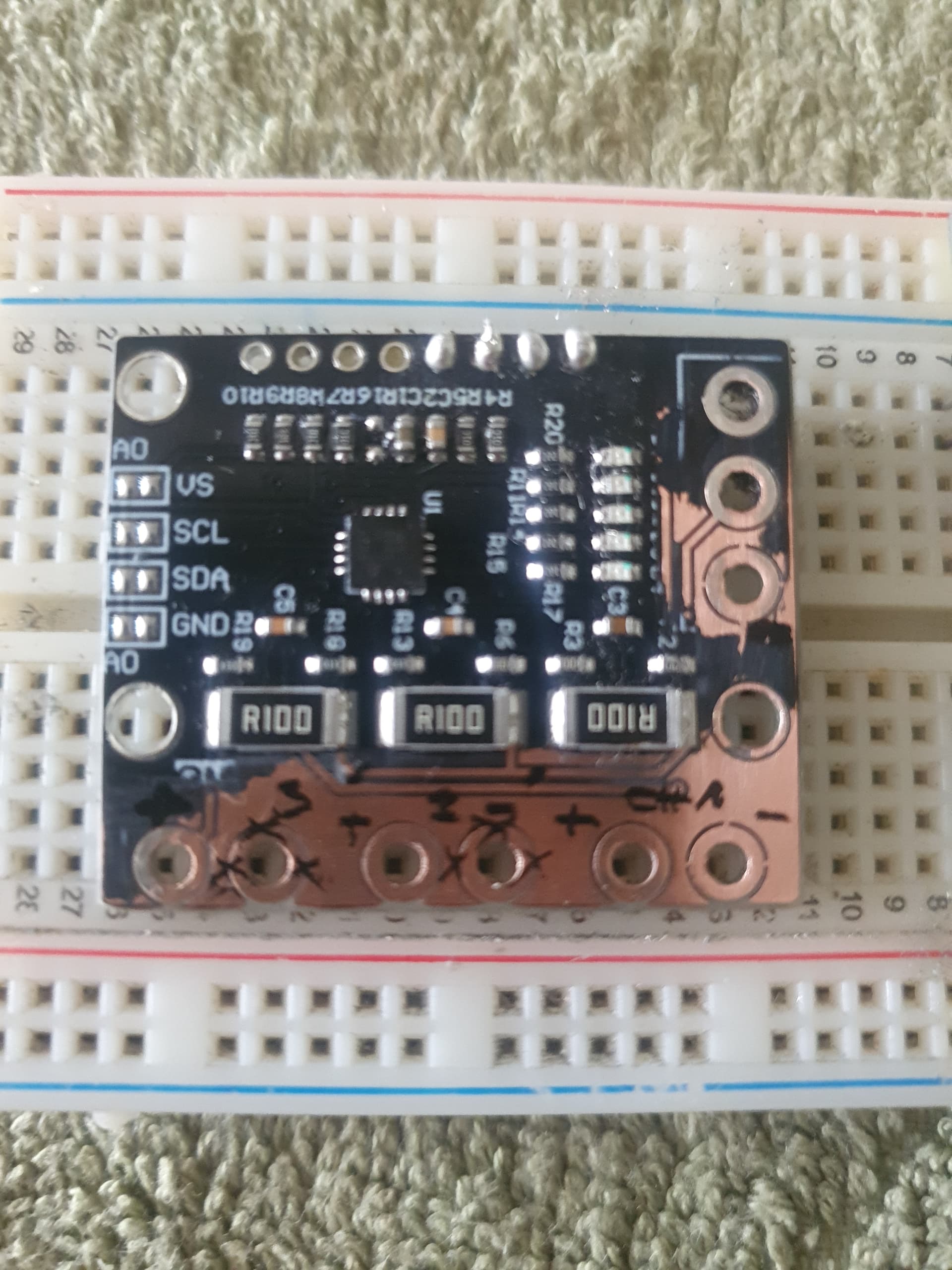
Not sure if that board will work correctly with those ground pads cut
Not only from a 12V anemometer, but also a 12V wind direction, and also battery load, all on a ESP8266 with solar charged battery. The ADC port is reserved for the raind sensor (not the rain volume - tippet bucket).
This way i would have a much simpler circuit (i2C) and simpler code. And so i saw in the INA3221 a feaseable way, as there are 3 channels (0V to 26V DC) on it, as i saw athe post from @R11K Fixing the INA3221 breakout board, which seems a way (dear @R11K , do you confirm?)
By connecting the 12V battery to POW and GND, i2c display shows 12V in all 3 channels.
But before frying the board (i tryed measure a battery and looked like a short was build), i'm asking...
Is the IN- input still connected to those pads after you cut the ground traces?
I don't think it is.
Which anemometer / weather station are you using?
i didn't cut anything yet, but will do. i
This one. 0V to 10V https://vi.aliexpress.com/item/1005005579975730.html?spm=a2g0o.order_list.order_list_main.270.21ef1802LBc4gs&gatewayAdapt=glo2vnm
And having a way to read it, as i think INA3221 may do, it's ideal, instead of working with voltage divider and limited ADC ports (1) from the 8266.
The picture shows that you cut the ground traces. Did you cut them or not?
according to Fixing the INA3221 breakout board - #18 by R11K, yes.
but i just want the voltage part (V!, V2 and V3) not the load (1, 2 and 3)...
@pw44
I don't see the jumper wires on your board. Where are they?
Once you put in the jumpers, the pad with the jumper will now be the IN- connection.
So if you follow my instructions in post #3, it will work.
Why not use an ADS1015 ADC module and a voltage divider. It's simpler to use, you will have more precision, extra channels and a lot less headache
I find out that the INA3221 breakout board have some serious design errors, so will not be suitable.
Even cutting the leads and creating new paths did not work well.
Replaced by two INA226 and it's working like acharm, 2 independent power sources.
Thank you for all the advises and help.
BTW, i also purchased an ADS1115 and will also give it a try, as i'm expanding the device and for sure will need ADC GPIO's (more than one).