IR Led climate control

Hi all, I have question for some problems.

I am trying to recieve climate controller data with TSOP1838 38 KHz IR.

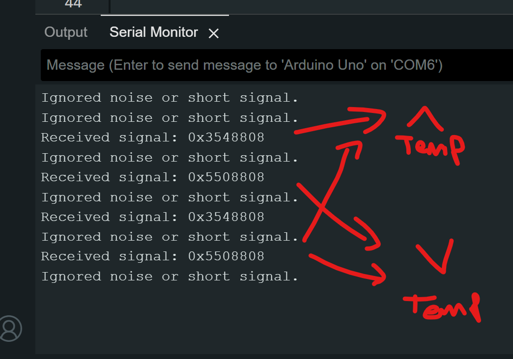
for example, When I push the temp+ button I am recieving always different Raw codes. is it normally? I read somewhere this is normally. after that, I try to send these raw codes to climate with IR Lcd modul. But the climate does not get to my send data.

this is my breadboard

What could I be doing wrong? Can you help me about it?

Depends. Can you post the raw data received?

Also, what kind of ir led module. Did you check with camera that it's illuminating when you try to send?

as you see on I shared picture, I use 5mm IR Led for send to data... But I am not sure breadboard connection is correct. also I am not sure for the receive raw data from climate controller. because, when I press a button, I see more than one message on serial monitor. I think all data does not came same time.

for example


#define RAW_DATA_LEN 60
uint16_t rawData[RAW_DATA_LEN]={
	3206, 9798, 518, 1566, 542, 494, 514, 518, 
	534, 498, 518, 1530, 518, 542, 518, 522, 
	518, 498, 518, 542, 514, 502, 514, 542, 
	518, 514, 494, 1582, 490, 542, 514, 526, 
	494, 550, 490, 1566, 514, 542, 494, 1570, 
	518, 526, 542, 514, 490, 542, 494, 550, 
	490, 542, 490, 554, 490, 522, 518, 1598, 
	490, 534, 514, 1000};
Do a cut-and-paste of the following lines into the 
designated location in rawSend.ino

#define RAW_DATA_LEN 2
uint16_t rawData[RAW_DATA_LEN]={
	34, 1000};

Maybe long pause is separating them... Try with this, ir receiver to arduino pin2.

/*
Connections:
IR Receiver      Arduino
V+          ->  +5v
GND          ->  GND
Signal Out   ->  Digital Pin 2
(If using a 3V Arduino, you may connect V+ to +3V)
*/

#define LEDPIN 13
//you may increase this value on Arduinos with greater than 2k SRAM
#define maxLen 800

volatile  unsigned int irBuffer[maxLen]; //stores timings - volatile because changed by ISR
volatile unsigned int x = 0; //Pointer thru irBuffer - volatile because changed by ISR

void setup() {
  Serial.begin(115200); //change BAUD rate as required
  attachInterrupt(0, rxIR_Interrupt_Handler, CHANGE);//set up ISR for receiving IR signal
}

void loop() {
  // put your main code here, to run repeatedly:

  Serial.println(F("Press the button on the remote now - once only"));
  delay(5000); // pause 5 secs
  if (x) { //if a signal is captured
    digitalWrite(LEDPIN, HIGH);//visual indicator that signal received
    Serial.println();
    Serial.print(F("Raw: (")); //dump raw header format - for library
    Serial.print((x - 1));
    Serial.print(F(") "));
    detachInterrupt(0);//stop interrupts & capture until finshed here
    for (int i = 1; i < x; i++) { //now dump the times
      if (!(i & 0x1)) Serial.print(F("-"));
      Serial.print(irBuffer[i] - irBuffer[i - 1]);
      Serial.print(F(", "));
    }
    x = 0;
    Serial.println();
    Serial.println();
    digitalWrite(LEDPIN, LOW);//end of visual indicator, for this time
    attachInterrupt(0, rxIR_Interrupt_Handler, CHANGE);//re-enable ISR for receiving IR signal
  }

}

void rxIR_Interrupt_Handler() {
  if (x > maxLen) return; //ignore if irBuffer is already full
  irBuffer[x++] = micros(); //just continually record the time-stamp of signal transitions

}

Also, what led it is? Is it 940nm ? From where?

Press the button on the remote now - once only

it does not recieve anything. I use to TSOP1838 38 KHz IR for recieving. Does it matter?

TSOP is good.
Did you wire it to Arduino pin 2?

Yes

And you didn't edit the code anyhow, right?
Then you have loose wire.

No I did not edit code. I just change pin. I do not think so. because I see the raw with another code.

/* rawR&cv.ino Example sketch for IRLib2
 *  Illustrate how to capture raw timing values for an unknow protocol.
 *  You will capture a signal using this sketch. It will output data the 
 *  serial monitor that you can cut and paste into the "rawSend.ino"
 *  sketch.
 */
// Recommend only use IRLibRecvPCI or IRLibRecvLoop for best results
#include <IRLibRecvPCI.h> 

IRrecvPCI myReceiver(2);//pin number for the receiver

void setup() {
  Serial.begin(115200);
  delay(2000); while (!Serial); //delay for Leonardo
  myReceiver.enableIRIn(); // Start the receiver
  Serial.println(F("Ready to receive IR signals"));
  myReceiver.setFrameTimeout(100000);
}

void loop() {
  //Continue looping until you get a complete signal received
  if (myReceiver.getResults()) { 
    Serial.println(F("Do a cut-and-paste of the following lines into the "));
    Serial.println(F("designated location in rawSend.ino"));
    Serial.print(F("\n#define RAW_DATA_LEN "));
    Serial.println(recvGlobal.recvLength,DEC);
    Serial.print(F("uint16_t rawData[RAW_DATA_LEN]={\n\t"));
    for(bufIndex_t i=1;i<recvGlobal.recvLength;i++) {
      Serial.print(recvGlobal.recvBuffer[i],DEC);
      Serial.print(F(", "));
      if( (i % 8)==0) Serial.print(F("\n\t"));
    }
    Serial.println(F("1000};"));//Add arbitrary trailing space
    myReceiver.enableIRIn();      //Restart receiver
  }
}

Receiver pin is hardcoded to 2
did you modify this line:

You shouldn't . It's not for receiver.

No, I didn't :slight_smile:

Okay, now it's like this... I press the button and one message after another comes up continuously.

Weird, that same code was working for me and for another person here two days ago...
Anyway, go back to your precedent code if it's working then...
You could try to raise that FrameTimeout to see if it can catch those two pieces together.

I keep getting messages. It's like it's coming from other lights around me. When I cover the receiver, the message doesn't come.

With which code?
Bad connection on breadboard and jumper wires?
Also strong natural/artificial light can cause some noise.

same with both codes. I have a monitor right next to my card. I really don't know. I can't understand why not.

I would clean your wiring...

when I write hex code, it seems right like this.

Looks valid signal. But you should receive it equally in raw.
Just fix your wires, so situation doesn't change every time you touch your board.

I see what looks to be a DHT22 Temperature/Humidity sensor and an Arduino Uno. This is where a schematic would be a big improvement over a picture of a birds nest of wiring. Why exactly are you using IR?

Ron