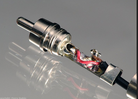
I am trying to get an existing project working, and it has two of these connectors (red and white), that I need to connect to a momentary push button.
Are these RCA connectors?
I've tried stripping and reusing an old audio cable I have, but I am confused since two wires go into each of the two connectors, and the audio cable I strip, only has one wire.
White: +3V and Digital Pin 2
Red: Ground and Digital Pin 4
Thanks! Some search terms to point me in the right direction would be very helpful.
Thanks! Is there a name for the cable to connect to it that would have two wires in the cable?
Or do I need another connector like this? Where one of each of those pins would map to each of the input cables (i.e. one for green and one for orange in the photo)?
Most of the cables that I have came from TVs or VCRs or ? and they ARE single conductors. They ALL have molded on RCA plugs on each end. They are ok for most signals if there is a ground connection somewhere between the devices. Test with an Ohmmeter from shield cover to shield cover. Mine only have continuity pin to pin.
That shouldn't happen with a pull-down resistor. The pull-down is supposed to hold the input low until it's "forced" high with an applied voltage.
An unconnected "floating" input (with no pull-up or pull-down) can literally float to an unknown voltage/state and it can read high or low. If you connect a wire that's unconnected on the other end you have an antenna that can pick-up noise and it might switch back-anf-forth between high and low and be even more unpredictable
Usually if you are going to connect an external switch through an RCA connector, The "outside" of the RCA connector is ground and the inside goes to a pull-up resistor. The input is normally pulled-high except when the switch is on, the input is forced low (to ground).
BTW - The Arduino has built-in pull-up resistors that you can enable so you don't have to add one if you can use a pull-up instead of a pull-down. (You just have to reverse the logic in your software.).
The RCA connector has two connections. The big-outside part is normally ground and the smaller inside contact is normally the signal.
With a regular audio cable the ground is normally the braided shield. It's a coaxial configuration with the signal wire surrounded by the ground/shield connection.
But not all RCA cables are shielded so you can simply have two wires, or there are other shielded cables with two or more wires plus a shield. But an RCA connector only has two connections, even if the cable has two wires plus a shield.
Of course you can use an RCA connector for almost anything you want, but they are normally used for audio/video signals on anything you buy.
Really helpful response - thanks so much! It's starting to make a little more sense now!
Presumably, while there is normally one signal and one ground, it's possible both are different signals? Such as in my case of the white connector, where the two wires to the connector are +3.5v and one that connects to pin 4 (used as an input to read the state of the button).
Thanks everyone else, I'm waiting for some parts to arrive but hopefully this is enough to get it working
All depends on the female part of the connector. Most have the ring connected to ground by the mounting method of the connector. If insulated from the chassis ground, then you can have two wires with different signals. That is REALLY POOR design, relying on the proper connectors and wire to be used and the same type connection being used on the device at the other end of the cable. That would ALSO be relying on some other wires to make the ground connection or make the complete circuit. If you find this to be the case, use some other devices that are properly designed.