Hello, @markd833 sorry for the long pause. So I bought the new RS485 Modbus module. The previous one was indeed faulty. All the test passed and the test that you suggested above was also passing, means TX and RX were same. I even connected the 7 in 1 soil moisture sensor and it was working correctly this means the system is fine. By system I meant The Arduino Module, The RS485 module and the sensor ( 7 in 1). I then proceeded to change the sensor to the shutter box as my original goal is to run the shutter box. I used the code
// Attempt to access a JXCT type NPK sensor to read registers 0x00 to 0x2F
// to see if there is any response from the NPK sensor.
//
// This attempt uses the AltSoftSerial & raw Modbus packets.
// Get AltSoftSerial at https://www.pjrc.com/teensy/td_libs_AltSoftSerial.html
//
// Also requires the CRC library by Rob Tillaart - install it via Library Manager
//
// RS485 module wired up as:
// RS485 DI signal to pin 9
// RS485 RO signal to pin 8
// RS485 RE signal to pin 7
// RS485 DE signal to pin 6
// RS485 VCC to 5V
// RS485 GND to GND
//

#include <AltSoftSerial.h>
#include "CRC16.h"
#define RE 7
#define DE 6

const uint32_t TIMEOUT = 500UL;

uint8_t msg[] = {0x01, 0x03, 0x00, 0x00, 0x00, 0x01, 0xC4, 0x0B};
uint8_t values[11];
uint8_t regAddr = 0;

AltSoftSerial swSerial;

CRC16 crc(CRC16_MODBUS_POLYNOME,
          CRC16_MODBUS_INITIAL,
          CRC16_MODBUS_XOR_OUT,
          CRC16_MODBUS_REV_IN,
          CRC16_MODBUS_REV_OUT);

void setup() {
  Serial.begin(4800);
  swSerial.begin(4800);
  pinMode(RE, OUTPUT);
  pinMode(DE, OUTPUT);
  digitalWrite(DE, LOW);
  digitalWrite(RE, LOW);

  Serial.println("\n\nModbus NPK register scanner.\n\n");
  delay(1000);
}

void loop() {
  uint32_t startTime = 0;
  uint16_t crcValue = 0;

  // insert the register address
  msg[ 3 ] = regAddr++;

  // generate the CRC16 Modbus checksum
  crc.restart();
  for (uint8_t i=0; i<sizeof( msg )-2; i++ ) {
    crc.add( msg[i] );
  }
  crcValue = crc.calc();

  // and insert it into the test message
  msg[ sizeof(msg)-2 ] = (crcValue & 0xFF);
  msg[ sizeof(msg)-1 ] = ((crcValue >> 8) & 0xFF);

  Serial.print("TX: ");
  printHexMessage( msg, sizeof(msg) );

  // send the command
  digitalWrite(DE, HIGH);
  digitalWrite(RE, HIGH);
  delay( 10 );
  swSerial.write( msg, sizeof(msg) );
  swSerial.flush();
  digitalWrite(DE, LOW);
  digitalWrite(RE, LOW);

  Serial.print("RX: ");

  // read any data received and print it out
  startTime = millis();
  while ( millis() - startTime <= TIMEOUT ) {
    if (swSerial.available()) {
      printHexByte(swSerial.read());
    }
  }
  Serial.println();
  delay(500);

  // reset register address back to 0x00 once we reach address 48
  if ( regAddr > 0x2F ) {
    regAddr = 0;
    Serial.println("\n\n\Rescan from register address 0x00 again in 5 seconds.\n\n");
    delay( 5000 );
  }
}

void printHexMessage( uint8_t values[], uint8_t sz ) {
  for (uint8_t i = 0; i < sz; i++) {
    printHexByte( values[i] );
  }
  Serial.print("  -   ");
}

void printHexByte(byte b)
{
  Serial.print((b >> 4) & 0xF, HEX);
  Serial.print(b & 0xF, HEX);
  Serial.print(' ');
}
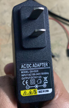
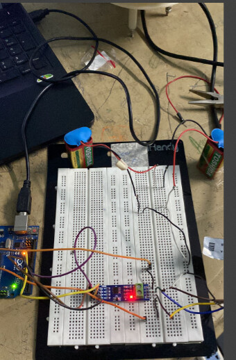
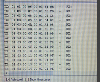
Now when I run the code I connected the Blue and Yellow pins to RS485 as intended and the brown (power) pin to my power supply ( in this case it's 7 volt battery since I am not in the lab) and black to GND, I got no response from the sensor so I disconnected the brown and black pins and connected the power supply adapter, the sensor did respond but I am not sure what to make of it I am sharing the response here
Output:
These two pics are the same response it was just that I was limited by the screen width.
Does this mean anything ? . Also I have this manual from the company which they gave me
485JXBS-8001-BYX-485-type-weather-shutter.pdf (481.2 KB)
Edit: this was the manual they gave and not the above one ( the above one I found on internet on their website )
JXCT-QXZ Weather Station Monitoring System.pdf (746.9 KB)
Can it be because I am not supplying enough power through brown and black wires like between 12v to 24v thats why it's happening ?