Hello good people of the Arduino forum.. I finally got around to registering after reading a fair few posts around here over the past couple of years.
Unfortunately, the main reason for registering is that I have come across a problem that I cant seem to get past.
I am trying to drive a motor with stall current of 2.5A bi-directionally with an Arduino Nano. I wanted to use the L298 (I tried two L293NE chips piggybacked but they were over heating), and wired the inputs and outputs in parallel to get it up to a max current capacity of 4A
I have wired the L298 exactly like this:
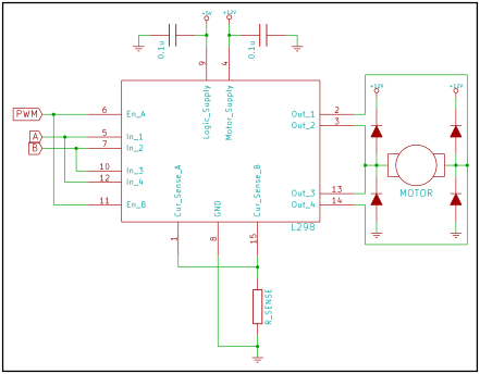
When I connect both of the Enable (EN) wires, one of the 'In' pairs (eg 'In 1' and 'In 4' together) and the logic supply to a regulated +5v supply, and the motor voltage supply to +9V, the motor runs just fine, and that works in both directions.
My problem arises when I try to connect the two EN wires and an 'In' pair to digital outs on my Arduino. I want both EN wires to be controlled by one Arduino pin for PWM, and each 'In' pair to be controlled by one pin each (simply set them to high or low). I believe the Arduino can't supply enough current to a single pin to drive 2 EN wires, or an 'In' pair.
For the moment, I am just trying to get the EN wires working (one step at a time!), so I've wired 'In 1 & 4' to the regulated +5V to make sure that is getting what it needs and left 'In 2&3' disconnected. I tried using a 2N3904 transistor with the Base on Pin 9 on my Arduino (Set to High in the extremely simply code), regulated +5V on the Collector and the EN wires connected to the Emitter, followed by a 10k resistor, then going to GND. The motor just runs constantly regardless of whether the Arduino is even connected or not and it seems to be ignoring the transistor which should be stopping the flow between the +5v and GND
Can anyone help please? I seem to have exhausted Google's capabilities searching for an answer. I did find this:
http://www.ikalogic.com/4a-h-bridge-motor-driver-using-the-l298-ic-schematic/
which is where I got the idea for the transistor, but I really want my EN wires and 'In' pairs kept separate from eachother.