Hi,
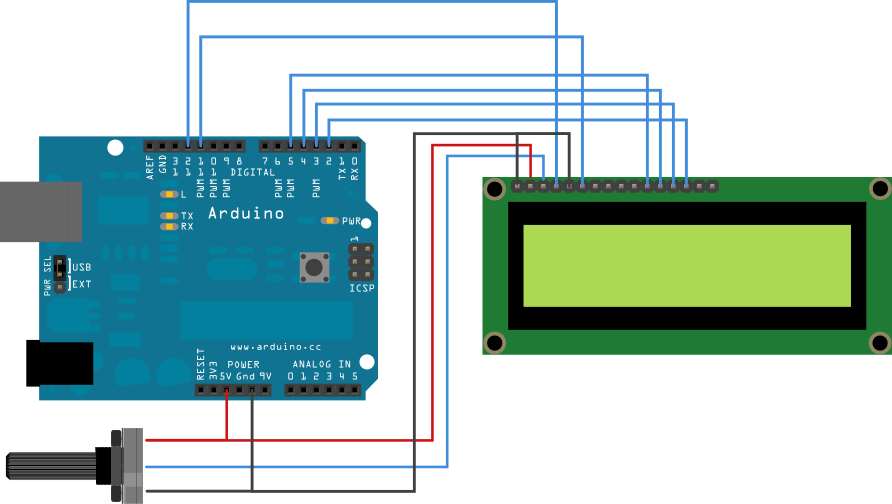
I'm a complete newb, and am just trying to do the Liquidcrystal - hello world! Without changing anything in the code. My LCD is dead and shows no signs if life. Here is my wiring:

Golux:
Hi,
I'm a complete newb, and am just trying to do the Liquidcrystal - hello world! Without changing anything in the code. My LCD is dead and shows no signs if life. Here is my wiring:
As i see the wiring is wrong.. Pin1 should be the Ground and pin2 should be Vcc(5V).. I didn't look further to your wiring.. Fix that and let me know what happens..
Pin1 should be the Ground and pin2 should be Vcc(5V).
For most, but not all, LCD modules.
Are the ICs or black blobs on the back of your LCD module getting very hot?
Don
floresta:
Pin1 should be the Ground and pin2 should be Vcc(5V).
For most, but not all, LCD modules.
Are the ICs or black blobs on the back of your LCD module getting very hot?
Don
i don't know if there are a few that don't, however i've never seen a different wiring on those simple 16X2 LCD's...
I'm pretty sure that if he swaps the ground with Vcc everything will work fine.. ![]()
As well as switching power and ground, you should hook up the backlight on pins 15/16. If there is a 101 resistor in R8 on the backside he should be fine either with a direct connection to the breadboard rails or an Arduino pin if he wants on/off control. If there is no resistor there, he should add one on the bread board.
I think it would be good practice to keep the data lines away from Pins 0,1,2 because of the conflict with Serial RX/TX and possible use of pin 2 for interrupts. I often use 4,5,6,7 for the data lines and that seems to stay away from most pin conflicts.
If you don't get "Hello World" going, please post your code so we can check out how you define the lcd constructor pin assignements and how you finally get it wired.
Good luck, and welcome to Arduino world.
cattledog:
As well as switching power and ground, you should hook up the backlight on pins 15/16. If there is a 101 resistor in R8 on the backside he should be fine either with a direct connection to the breadboard rails or an Arduino pin if he wants on/off control. If there is no resistor there, he should add one on the bread board.
An 100 Ohm resistance would be ok ?
Choosing the perfect back light resistor involves knowledge of the specific led in the display and whether it is powered from the breadboard rails or an output pin which has less current capability.
Powering the led from the 5v and ground, anything from 330 to 100 should be OK and will get the OP up and running. If the display is too dim, he can use a smaller one.
cattledog:
Choosing the perfect back light resistor involves knowledge of the specific led in the display and whether it is powered from the breadboard rails or an output pin which has less current capability.Powering the led from the 5v and ground, anything from 330 to 100 should be OK and will get the OP up and running. If the display is too dim, he can use a smaller one.
For a 5V LCD where the backlight operates on 4.2V and we have a supply currnet of max 2.5mA then a 330 Ohm resistor is appropriate..
I fixed the wiring and nothing happened. I will see if the black blobs get hot, and try to hook up the backlight. Just for clarification, I should try to get some sign of life before I 'get fancy' with backlights?
Golux:
I fixed the wiring and nothing happened. I will see if the black blobs get hot, and try to hook up the backlight. Just for clarification, I should try to get some sign of life before I 'get fancy' with backlights?
There is no need to wire the back light yet, LCD can work without it too.. I would advise you to check the wiring again...
Also don't use RX/TX pins as suggested earlier , use others instead and check your code again..
Here is the sketch I am working off.

Just scared I'm not wiring what I'm supposed to in the first place, inserting a bread board into the mix.
Here is the code:
/*
LiquidCrystal Library - Hello World
Demonstrates the use a 16x2 LCD display. The LiquidCrystal
library works with all LCD displays that are compatible with the
Hitachi HD44780 driver. There are many of them out there, and you
can usually tell them by the 16-pin interface.
This sketch prints "Hello World!" to the LCD
and shows the time.
The circuit:
- LCD RS pin to digital pin 12
- LCD Enable pin to digital pin 11
- LCD D4 pin to digital pin 5
- LCD D5 pin to digital pin 4
- LCD D6 pin to digital pin 3
- LCD D7 pin to digital pin 2
- LCD R/W pin to ground
- 10K resistor:
- ends to +5V and ground
- wiper to LCD VO pin (pin 3)
Library originally added 18 Apr 2008
by David A. Mellis
library modified 5 Jul 2009
by Limor Fried (http://www.ladyada.net)
example added 9 Jul 2009
by Tom Igoe
modified 22 Nov 2010
by Tom Igoe
This example code is in the public domain.
*/
// include the library code:
#include <LiquidCrystal.h>
// initialize the library with the numbers of the interface pins
LiquidCrystal lcd(12, 11, 5, 4, 3, 2);
void setup() {
// set up the LCD's number of columns and rows:
lcd.begin(16, 2);
// Print a message to the LCD.
lcd.print("hello, world!");
}
void loop() {
// set the cursor to column 0, line 1
// (note: line 1 is the second row, since counting begins with 0):
lcd.setCursor(0, 1);
// print the number of seconds since reset:
lcd.print(millis()/1000);
}
Golux:
Here is the sketch I am working off.http://arduino.cc/en/uploads/Tutorial/LCD_bb.png
Just scared I'm not wiring what I'm supposed to in the first place, inserting a bread board into the mix
well make sure the wiring is right..
First thing is to please read the "How to use this forum' and learn how to use code tags. It will save a lot of frustration on the part of those trying to help you.
You may need to turn the contrast pot which connects to pin 3 of the lcd back and forth to see if you can get it to where some boxes show up, and then you can fine tune it to get the printout to show.
Your initial wiring was not consistent with the sketch you posted, so lets see another picture of the revised wiring and the code you are actually trying to run.
Just scared I'm not wiring what I'm supposed to in the first place, inserting a bread board into the mix
Have courage. Your not the first person in your position, and I believe that everyone who has been there has come out the other side looking at "Hello World".
Just connect power to pins 1 and 2 and see if the ICs or black blobs on the back of your LCD module are getting very hot.
If they are hot then reverse pins 1 and 2 and check again.
When the device is cool with the power applied you can follow the rest of my generic procedure.
Here is my generic step by step approach that should work:
(1) If the module has a backlight then get it working properly. This involves only pins 15 and 16 on most LCD modules. Make sure to use a current limiting resistor if there is none on the LCD module.
(2) Get the power and contrast working properly. This involves only pins 1, 2, and 3 on most LCD modules. You should be able to just barely see blocks on one row of a two row display and on two rows of a four row display.
NOTE: The Arduino has not been used yet, except as a possible source for the power needed for the first two steps. Do not try to go any further until this is working. If you don't see the blocks then no amount of program code will help.
(3) Connect the LCD R/W pin (pin 5) to GND.
(4) Connect the six control and data wires between your LCD module and your Arduino.
(5) Upload your sketch and it should work.
Troubleshooting:
If you have a 16x1 display and there are blocks only on the left half of the row in step 2 then use
lcd.begin(8, 2);
in your sketch.
If you still don't get a display then make sure that your wiring matches the numbers in the descriptor (or vice versa).
//LiquidCrystal lcd(RS, E, D4, D5, D6, D7);
LiquidCrystal lcd(7, 8, 9, 10, 11, 12);      // put your pin numbers here
If you get a display but it is garbled or has some other problems then try again with a 'static' sketch, one that displays a simple message on the top row of the display and then stops. All of your code should be in setup() and loop() should be empty between the brackets.
#include <LiquidCrystal.h>

//LiquidCrystal lcd(RS, E, D4, D5, D6, D7);
LiquidCrystal lcd(7, 8, 9, 10, 11, 12);      // put your pin numbers here

void setup()
  {
  lcd.begin(16, 2);                          // put your LCD parameters here
  lcd.print("hello, world!");
  lcd.setCursor(0,1);
  lcd.print("it works!");
  }

void loop()
  {
  }
If you are still having problems then we need to see a photograph of your setup that clearly and unambiguously shows all of the connections between your Arduino and your LCD module. We also need a copy/paste version of the code that you are actually using, not a link to the code that you think you are using.
Don
Thank you so much for your help. It was greatly beneficial and the sketch is now working.
It is quite dim though, and as you can see it can barely be read even with the contrast turned up all the way. I tried powering the backlight with/without a resistor to no avail.
Any clues?

Tinkering with the backlight won't help here. Most likely you have an 'extended' temperature range LCD module. Most of those require a negative voltage (with respect to GND) at pin 3.
You can check this out with the help of a small battery. Disconnect the end of your potentiometer from GND and connect it to the negative end of your battery. Connect the positive end of the battery to GND. Now you can use the potentiometer to lower the voltage at pin 3 below 0 volts and see if the display improves.
Don

Get the battery (or a second power supply) connected permanently and then troubleshoot the new problem. You may find that it goes away when you keep your hands away from the wiring.
Don
Guys,
I have the same abovd problem, the only thing i get on the LCD is a black boxes on the above row of the LCD. i have tried all the above mentioned solutions but nothing happened.
Since you have resurrected an old thread it is obvious that you did look through the forum which is always a good choice.
BUT - You do not have the same problem since your display shows a row of blocks whereas this thread is about a device that appeared dead with nothing on the display.
My suggestion is for you to try my generic procedure outlined in reply #13. If that doesn't work for you then start a new thread and include a photograph of your connections that allows us to unambiguously follow each wire from one end to the other.
Don