I am a beginner with electronics and hardware. I am trying to connect a pulse oximeter sensor to my Arduino, however no matter which library I use I cannot form a connection.
I have never seen the LED on the sensor light up. I am not sure if it is supposed to do this or not.
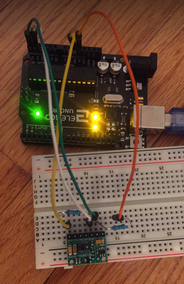
Attached is a photo of my circuit diagram. I followed various guides online which all said to connect 3.3V from Arduino to VIN, GND to GND, A4 from Arduino to SDA, A5 from Arduino to SCL.
I have tried re-wiring the system and pulling up the SCL and SDA lines with 5K and 2K resistors (although I should not have to do this with the purple hardware, the green one in the photo requires it but also doesn't work either way). I'm not sure if I pulled up the line properly.
Breadboard that came with the ELEGOO, not the best quality. Tough to use and damages wires. Waiting on the arrival of a new one thats hopefully better.
Software libraries tried:
Arduino-MAX30100 (says failed to connect)
SparkFun MAX3010x Sensor Library
("MAX30105 was not found. Please check wiring/power. " This library should work w/both 30105 and 30102)
MAX30100 (Says I have the correct part id, 0xff, I2C error)
Is there something wrong with my sensor? I am confused as to why I cannot instantiate a connection. Any help is appreciated.
Please let me know if there is more information I can provide.
The MAX30102 is a device that needs a 3.3V and a 1.8V supply. Additionally it's available only in an SMD casing so I'm quite sure you don't use the chip directly but some breakout board. I guess that board includes additional circuitry but you failed to provide information to that.
avainslie__:
I am a beginner with electronics and hardware.
Welcome to the Arduino world.
Thank you for the links and the drawing
At this point we don't care about tutorials or libraries or what other websites say. We need to know what you have.
Is this your module ? https://www.amazon.com/HiLetgo-MAX30102-Breakout-Oximetry-Solution/dp/B07QC67KMQ.
That is very nice, it has two voltage regulators and a I2C level shifter on the back.
It will work better when you apply the Arduino 5V to the module VIN. If you use 3.3V, then the I2C level shifters don't work.
It has already enough pullup resistors for the I2C bus, you don't have to add extra pullup resistors.
Is this the Starter Kit that you have ? ELEGOO UNO R3 Super Starter Kit with Tutorial Compatible with Arduino IDE – ELEGOO Official.
The Uno clone is probably okay.
The cheap breadboards have often bad contacts and jumper wires can be broken. That causes a lot of problems. It seems to increase every year. When you buy another cheap breadboard, then it is just as bad.
Can you power the Arduino board with the USB cable ? Please remove the 9V battery.
If nothing helps, can you make a photo of it that shows the wiring ?
Links have sometimes tracking information or some rubbish from the site. It is often possible to shorten them.
The link to the first tutorial can be this: Interfacing MAX30100 Pulse Oximeter Sensor with Arduino
At Youtube, you can click the "Share" button and use that or use this: https://www.youtube.com/watch?v=8SOTsR1k8-g
I get nauseous within 5 seconds because of that robot voice. Is that just me ?
I am unfamiliar with the circuitry of the module, but it is the MAX30102 linked in the second comment.
The UNO clone linked in the same comment is the one I have as well.
Update:
I am now trying both 5 V and 3.3 V from Arduino to module VIN with everything I do just in case. I have also removed the 9 V battery and only use USB to power the Arduino.
I also received a new breadboard which you will see the details of in the second photo. It works much better than the one that came with the UNO clone.
As for the I2C Scanner I mainly received "No I2C devices found". However "Unknown error at address 0x01" and "Unknown error at address 0x15" displayed once each. Eventually the scanner started to hang and didn't provide any information. Tried uploading Blink sketch and then re-uploading the I2C Scanner, but it was still hanging.
I tried a cheap MAX30100 with the new breadboard and was able to see a few blinks of the LED! The wiring of this is shown in the third image and the resistors are 2 K. Only "No I2C devices found" with the I2C Scanner.
I am wondering if the MAX30102 is simply broken? I am happy to provide any information I may have missed.
Photos:
First one is my setup yesterday.
Second is my current MAX30102 setup w/information about the new breadboard.
Third is my MAX30100 setup.
Do you have a multimeter and a soldering iron ?
A multimeter is also called "DMM", but in my country it is only called a "multimeter".
A soldering station with adjustable temperature and a soldering iron with a active tip is the best. The "active tip" is sometimes called "new generation" or "direct heating". A Hakko station with T12 tips is good. There are cheap soldering stations with cheap T12 clones, they are not so bad either. Use lead-free solder and always have good ventilation when soldering.
You have to check if the jumper wires are not broken.
You have to solder the pins to the modules.
The Arduino VIN pin is to power the Arduino board. When you have the 9V battery attached to the barrel jack, then VIN is almost 9V. When you connect the Arduino VIN to any pin of the module, then it is probably instantly broken. You could even have damaged the Arduino itself, because the SDA and SCL were connected to that module.
It is therefor safer to use only 5V from the USB cable. When someone starts with motors and 12V, then a mistake happens easy. You are not the first one that damages something with a voltage higher than 5V