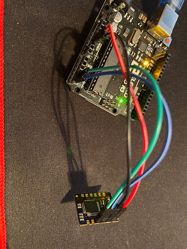
Hey, I am trying to use the MAX30102 Oximeter sensor from Maxim (sensor) with an Elegoo Uno R3 board (exact model). I have all necessary connections soldered on to the sensor and connected to the board.
I tried running the starter code given by DFRobot's MAX30120 library below:
/*!
 * @file basicRead.ino
 * @brief Output readings of red light and IR
 * @n This library supports mainboards: ESP8266, FireBeetle-M0, UNO, ESP32, Leonardo, Mega2560
 * @copyright  Copyright (c) 2010 DFRobot Co.Ltd (http://www.dfrobot.com)
 * @licence     The MIT License (MIT)
 * @author [YeHangYu](hangyu.ye@dfrobot.com)
 * @version  V0.1
 * @date  2020-05-29
 * @url https://github.com/DFRobot/DFRobot_MAX30102
 */

#include <DFRobot_MAX30102.h>

DFRobot_MAX30102 particleSensor;

/*
Macro definition opions in sensor configuration
sampleAverage: SAMPLEAVG_1 SAMPLEAVG_2 SAMPLEAVG_4
               SAMPLEAVG_8 SAMPLEAVG_16 SAMPLEAVG_32
ledMode:       MODE_REDONLY  MODE_RED_IR  MODE_MULTILED
sampleRate:    PULSEWIDTH_69 PULSEWIDTH_118 PULSEWIDTH_215 PULSEWIDTH_411
pulseWidth:    SAMPLERATE_50 SAMPLERATE_100 SAMPLERATE_200 SAMPLERATE_400
               SAMPLERATE_800 SAMPLERATE_1000 SAMPLERATE_1600 SAMPLERATE_3200
adcRange:      ADCRANGE_2048 ADCRANGE_4096 ADCRANGE_8192 ADCRANGE_16384
*/
void setup()
{
  //Init serial
  Serial.begin(115200);
  /*!
   *@brief Init sensor
   *@param pWire IIC bus pointer object and construction device, can both pass or not pass parameters (Wire in default)
   *@param i2cAddr Chip IIC address (0x57 in default)
   *@return true or false
   */
  while (!particleSensor.begin()) {
    Serial.println("MAX30102 was not found");
    delay(1000);
  }

  /*!
   *@brief Use macro definition to configure sensor
   *@param ledBrightness LED brightness, default value: 0x1F(6.4mA), Range: 0~255(0=Off, 255=50mA)
   *@param sampleAverage Average multiple samples then draw once, reduce data throughput, default 4 samples average
   *@param ledMode LED mode, default to use red light and IR at the same time
   *@param sampleRate Sampling rate, default 400 samples every second
   *@param pulseWidth Pulse width: the longer the pulse width, the wider the detection range. Default to be Max range
   *@param adcRange Measurement Range, default 4096 (nA), 15.63(pA) per LSB
   */
  particleSensor.sensorConfiguration(/*ledBrightness=*/0x1F, /*sampleAverage=*/SAMPLEAVG_4, \
                                  /*ledMode=*/MODE_MULTILED, /*sampleRate=*/SAMPLERATE_400, \
                                  /*pulseWidth=*/PULSEWIDTH_411, /*adcRange=*/ADCRANGE_4096);
}

void loop()
{
  //Print result
  Serial.print("R=");
  /*!
   *@brief Get red value
   *@return Red light reading
   */
  Serial.print(particleSensor.getRed());
  Serial.print(" IR=");
  /*!
   *@brief Get IR value
   *@return IR reading
   */
  Serial.print(particleSensor.getIR());
  Serial.println();
  delay(100);
}
But I get the following:
MAX30102 was not found
When I tried to run SparkFun's library:
/*
  Optical Heart Rate Detection (PBA Algorithm) using the MAX30105 Breakout
  By: Nathan Seidle @ SparkFun Electronics
  Date: October 2nd, 2016
  https://github.com/sparkfun/MAX30105_Breakout

  This is a demo to show the reading of heart rate or beats per minute (BPM) using
  a Penpheral Beat Amplitude (PBA) algorithm.

  It is best to attach the sensor to your finger using a rubber band or other tightening
  device. Humans are generally bad at applying constant pressure to a thing. When you
  press your finger against the sensor it varies enough to cause the blood in your
  finger to flow differently which causes the sensor readings to go wonky.

  Hardware Connections (Breakoutboard to Arduino):
  -5V = 5V (3.3V is allowed)
  -GND = GND
  -SDA = A4 (or SDA)
  -SCL = A5 (or SCL)
  -INT = Not connected

  The MAX30105 Breakout can handle 5V or 3.3V I2C logic. We recommend powering the board with 5V
  but it will also run at 3.3V.
*/

#include <Wire.h>
#include "MAX30105.h"

#include "heartRate.h"

MAX30105 particleSensor;

const byte RATE_SIZE = 4; //Increase this for more averaging. 4 is good.
byte rates[RATE_SIZE]; //Array of heart rates
byte rateSpot = 0;
long lastBeat = 0; //Time at which the last beat occurred

float beatsPerMinute;
int beatAvg;

void setup()
{
  Serial.begin(115200);
  Serial.println("Initializing...");

  // Initialize sensor
  if (!particleSensor.begin()) //Use default I2C port, 400kHz speed
  {
    Serial.println("MAX30105 was not found. Please check wiring/power. ");
    while (1);
  }
  Serial.println("Place your index finger on the sensor with steady pressure.");

  particleSensor.setup(); //Configure sensor with default settings
  particleSensor.setPulseAmplitudeRed(0x0A); //Turn Red LED to low to indicate sensor is running
  particleSensor.setPulseAmplitudeGreen(0); //Turn off Green LED
}

void loop()
{
  long irValue = particleSensor.getIR();

  if (checkForBeat(irValue) == true)
  {
    //We sensed a beat!
    long delta = millis() - lastBeat;
    lastBeat = millis();

    beatsPerMinute = 60 / (delta / 1000.0);

    if (beatsPerMinute < 255 && beatsPerMinute > 20)
    {
      rates[rateSpot++] = (byte)beatsPerMinute; //Store this reading in the array
      rateSpot %= RATE_SIZE; //Wrap variable

      //Take average of readings
      beatAvg = 0;
      for (byte x = 0 ; x < RATE_SIZE ; x++)
        beatAvg += rates[x];
      beatAvg /= RATE_SIZE;
    }
  }

  Serial.print("IR=");
  Serial.print(irValue);
  Serial.print(", BPM=");
  Serial.print(beatsPerMinute);
  Serial.print(", Avg BPM=");
  Serial.print(beatAvg);

  if (irValue < 50000)
    Serial.print(" No finger?");

  Serial.println();
}
I would get the following:
MAX30105 was not found. Please check wiring/power.
I ran the I2C Scanner and found the device at address 0x57.
Below is my circuit.
Documentation for MAX30102
Documentation for Elegoo Uno R3
This is my first time delving into the world of electronics so if it's something really basic, I apologise.

