When i uploaded the code and powered the MAX7219 chip,
all segment's leds are lit. and not controlled as code
leds are all turning off after MCU disconnected.
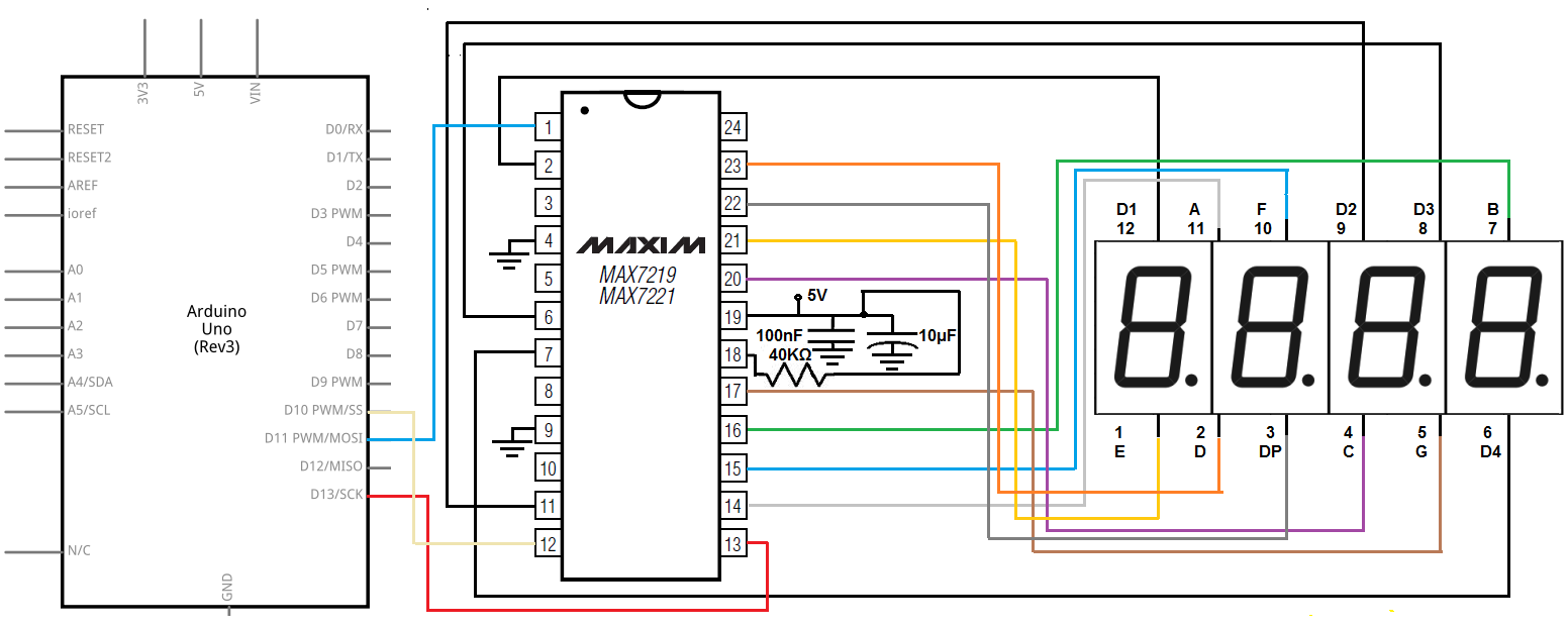
Im using max7219 ,common cathode 7-segment display, and esp32 devboard. also power supply for provide 5 volt to max7219
i connected them as pinout i found on internet, including two bypass capacitor.
Following the forum's advice, i added 10k pull-up register on cs pin.
and here is the code currently uploaded
#define MAX7219_Data_IN 32
#define MAX7219_Chip_Select  33
#define MAX7219_Clock 25

byte adr = 0x08;
byte num = 0x00;
int i = 0;

void shift(byte send_to_address, byte send_this_data)
{
  digitalWrite(MAX7219_Chip_Select, LOW);
  shiftOut(MAX7219_Data_IN, MAX7219_Clock, MSBFIRST, send_to_address);
  shiftOut(MAX7219_Data_IN, MAX7219_Clock, MSBFIRST, send_this_data);
  digitalWrite(MAX7219_Chip_Select, HIGH);
}


void setup() {
  pinMode(MAX7219_Data_IN, OUTPUT);
  pinMode(MAX7219_Chip_Select, OUTPUT);
  pinMode(MAX7219_Clock, OUTPUT);
  digitalWrite(MAX7219_Clock, HIGH);
  delay(200);

  //Setup of MAX7219 chip
  shift(0x0f, 0x00); //display test register - test mode off
  shift(0x0c, 0x01); //shutdown register - normal operation
  shift(0x0b, 0x07); //scan limit register - display digits 0 thru 7
  shift(0x0a, 0x0f); //intensity register - max brightness
  shift(0x09, 0xff); //decode mode register - CodeB decode all digits

}

void loop() {

  //Data transfer
  shift(0x08, 0x00); //digit 7 (leftmost digit) data
  shift(0x07, 0x01);
  shift(0x06, 0x02);
  shift(0x05, 0x03);
  shift(0x04, 0x04);
  shift(0x03, 0x05);
  shift(0x02, 0x06);
  shift(0x01, 0x07); //digit 0 (rightmost digit) data
  delay(1000);
  shift(0x08, 0x07); //digit 7 (leftmost digit) data
  shift(0x07, 0x06);
  shift(0x06, 0x05);
  shift(0x05, 0x04);
  shift(0x04, 0x03);
  shift(0x03, 0x02);
  shift(0x02, 0x01);
  shift(0x01, 0x00); //digit 0 (rightmost digit) data
  delay(1000);
}
other similar codes are tried. but all LEDs are still constantly on.
i followed some advice from forum, like checking whether segment is common anode. or adding pull up register on cs node, change to usable GPIO pin on esp32 board. but didnt work on my case
Please let me know if there is anything I forgot or made a mistake.
also, please let me know if there are better category classification. this project is about LED but not using arduino board.
